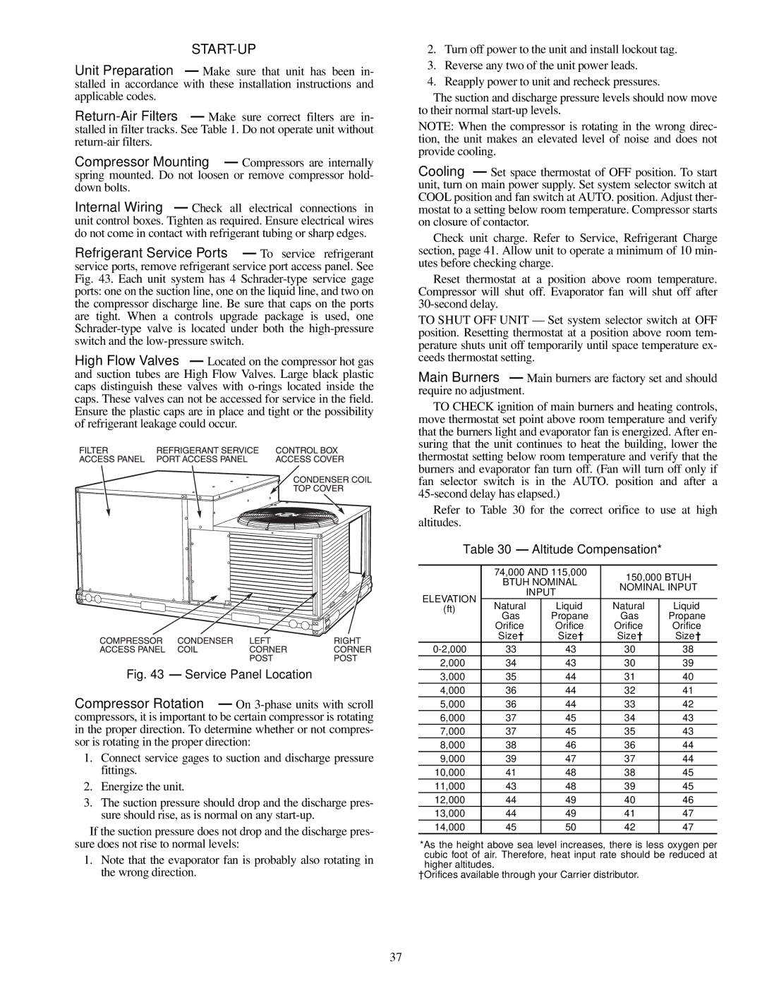
Safety Relief — A soft solder joint at the suction service Schrader port provides pressure relief under abnormal tempera- ture and pressure conditions (i.e., fire in building). Use backup wrench when tightening flare cap.
High Flow Valves — Located on the compressor hot gas and suction tubes are High Flow Valves. Large black plastic caps distinguish these valves with O-rings located inside the caps. These valves cannot be accessed for service in the field. Ensure the plastic caps are in place and tight or the possibility of refrigerant leakage could occur.
Ventilation (Continuous Fan) — Set fan and system selector switches at ON and OFF positions, respectively. Evaporator fan operates continuously to provide constant air circulation. When the evaporator-fan selector switch is turned to the OFF position, there is a 30-second delay before the fan turns off.
Operating Sequence
COOLING, UNITS WITHOUT ECONOMIZER — When thermostat calls for cooling, terminals G and Y1 are energized, and the indoor (evaporator) fan motor (IFM), compressor, and outdoor (condenser) fan motor (OFM start. The OFM runs con- tinuously while the unit is in cooling. When the thermostat is satisfied, compressor contactor (C) is deenergized and the com- pressor and OFM shut off. After a 30-second delay, the IFM shuts off. If the thermostat fan selector switch is the ON posi- tion, the evaporator motor will run continuously.
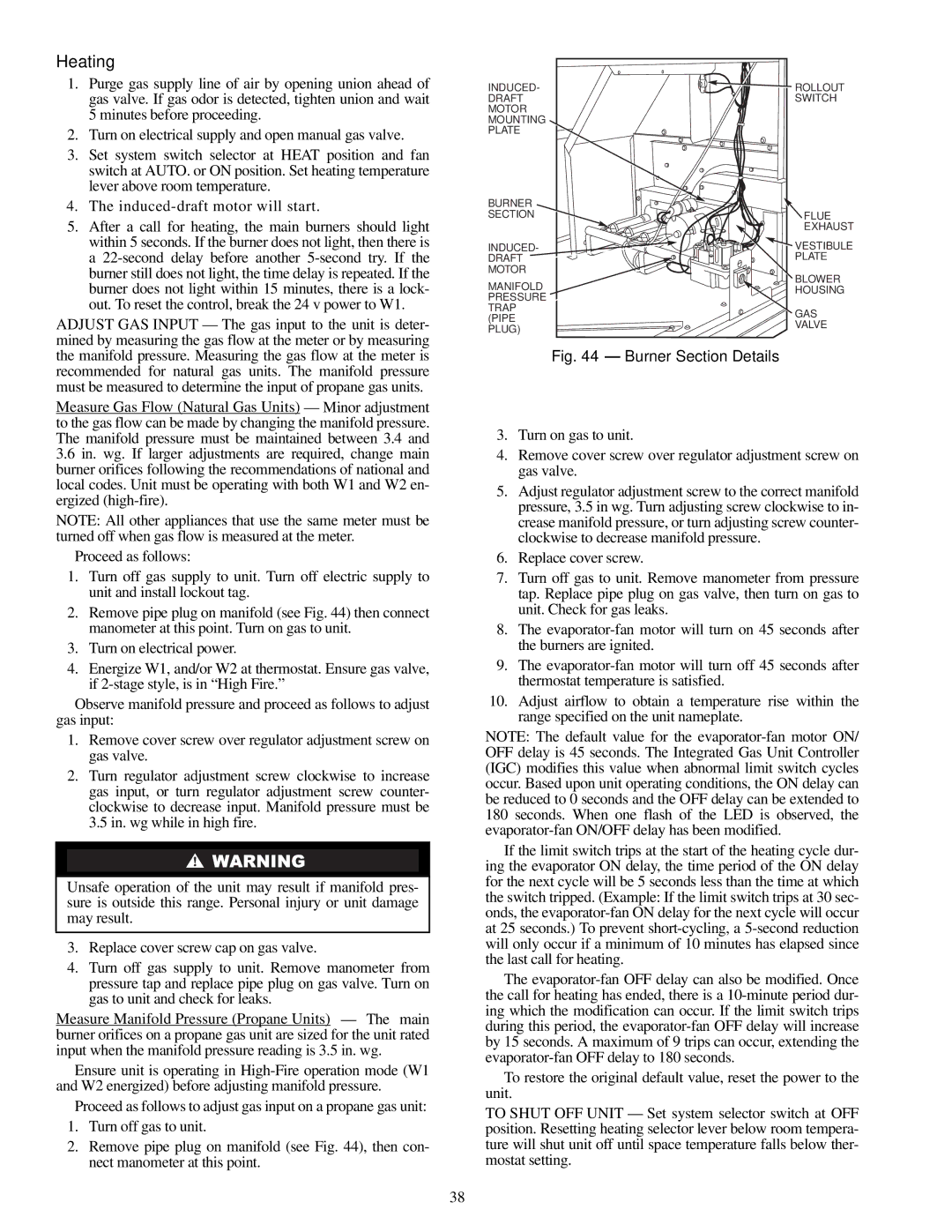
HEATING, UNITS WITHOUT ECONOMIZER — When the thermostat calls for heating, terminal W1 is energized. To prevent thermostat short-cycling, the unit is locked into the Heating mode for at least 1 minute when W1 is energized. The induced-draft motor is energized and the burner ignition se- quence begins. The indoor (evaporator) fan motor (IFM) is en- ergized 45 seconds after a flame is ignited. On units equipped for two stages of heat, when additional heat is needed, W2 is energized and the high-fire solenoid on the main gas valve (MGV) is energized. When the thermostat is satisfied and W1 is deenergized, the IFM stops after a 45-second time-off delay.
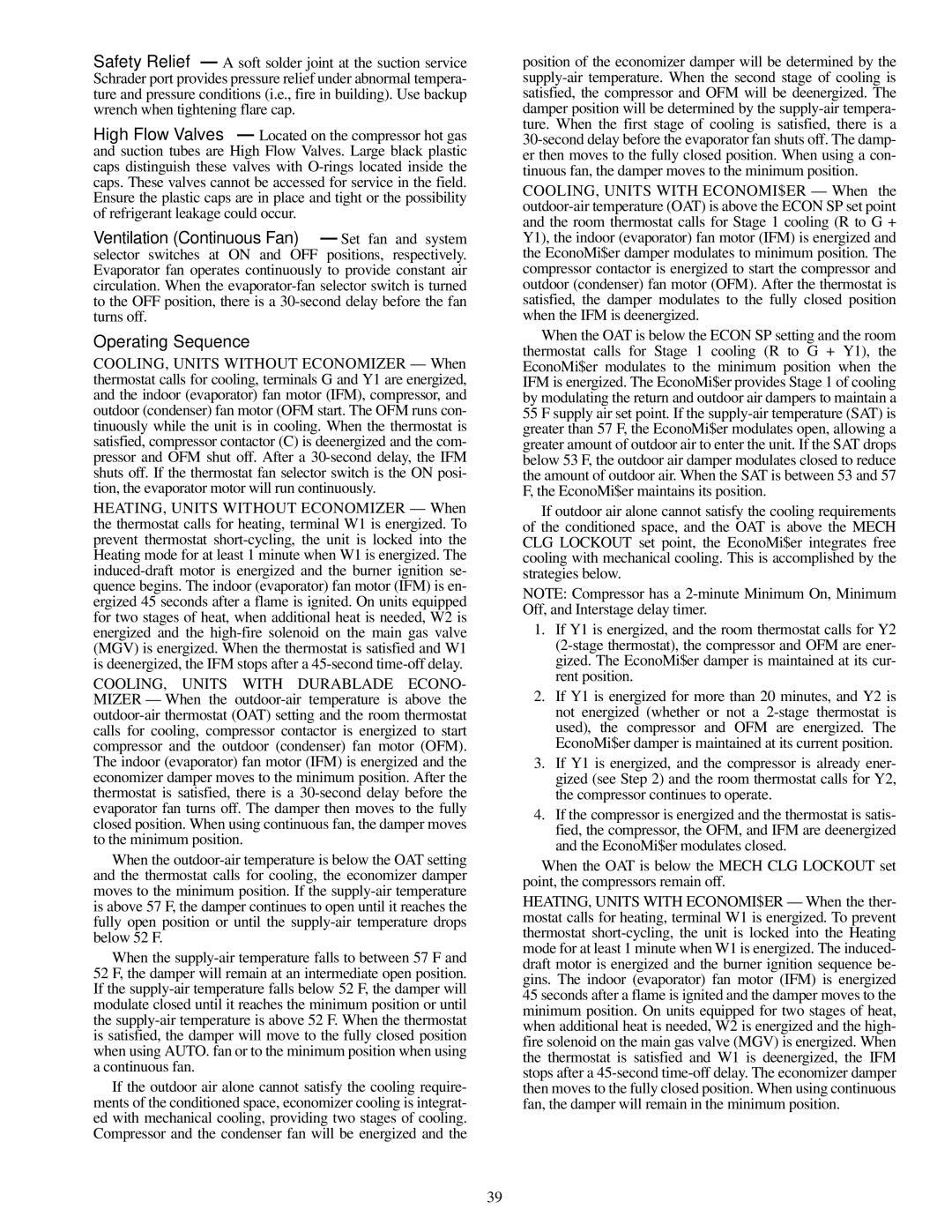
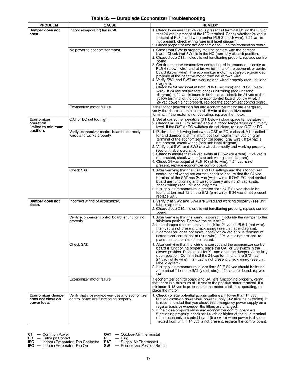
COOLING, UNITS WITH DURABLADE ECONO- MIZER — When the outdoor-air temperature is above the outdoor-air thermostat (OAT) setting and the room thermostat calls for cooling, compressor contactor is energized to start compressor and the outdoor (condenser) fan motor (OFM). The indoor (evaporator) fan motor (IFM) is energized and the economizer damper moves to the minimum position. After the thermostat is satisfied, there is a 30-second delay before the evaporator fan turns off. The damper then moves to the fully closed position. When using continuous fan, the damper moves to the minimum position.
When the outdoor-air temperature is below the OAT setting and the thermostat calls for cooling, the economizer damper moves to the minimum position. If the supply-air temperature is above 57 F, the damper continues to open until it reaches the fully open position or until the supply-air temperature drops below 52 F.
When the supply-air temperature falls to between 57 F and
52 F, the damper will remain at an intermediate open position. If the supply-air temperature falls below 52 F, the damper will modulate closed until it reaches the minimum position or until the supply-air temperature is above 52 F. When the thermostat is satisfied, the damper will move to the fully closed position when using AUTO. fan or to the minimum position when using a continuous fan.
If the outdoor air alone cannot satisfy the cooling require- ments of the conditioned space, economizer cooling is integrat- ed with mechanical cooling, providing two stages of cooling. Compressor and the condenser fan will be energized and the
position of the economizer damper will be determined by the supply-air temperature. When the second stage of cooling is satisfied, the compressor and OFM will be deenergized. The damper position will be determined by the supply-air tempera- ture. When the first stage of cooling is satisfied, there is a 30-second delay before the evaporator fan shuts off. The damp- er then moves to the fully closed position. When using a con- tinuous fan, the damper moves to the minimum position.
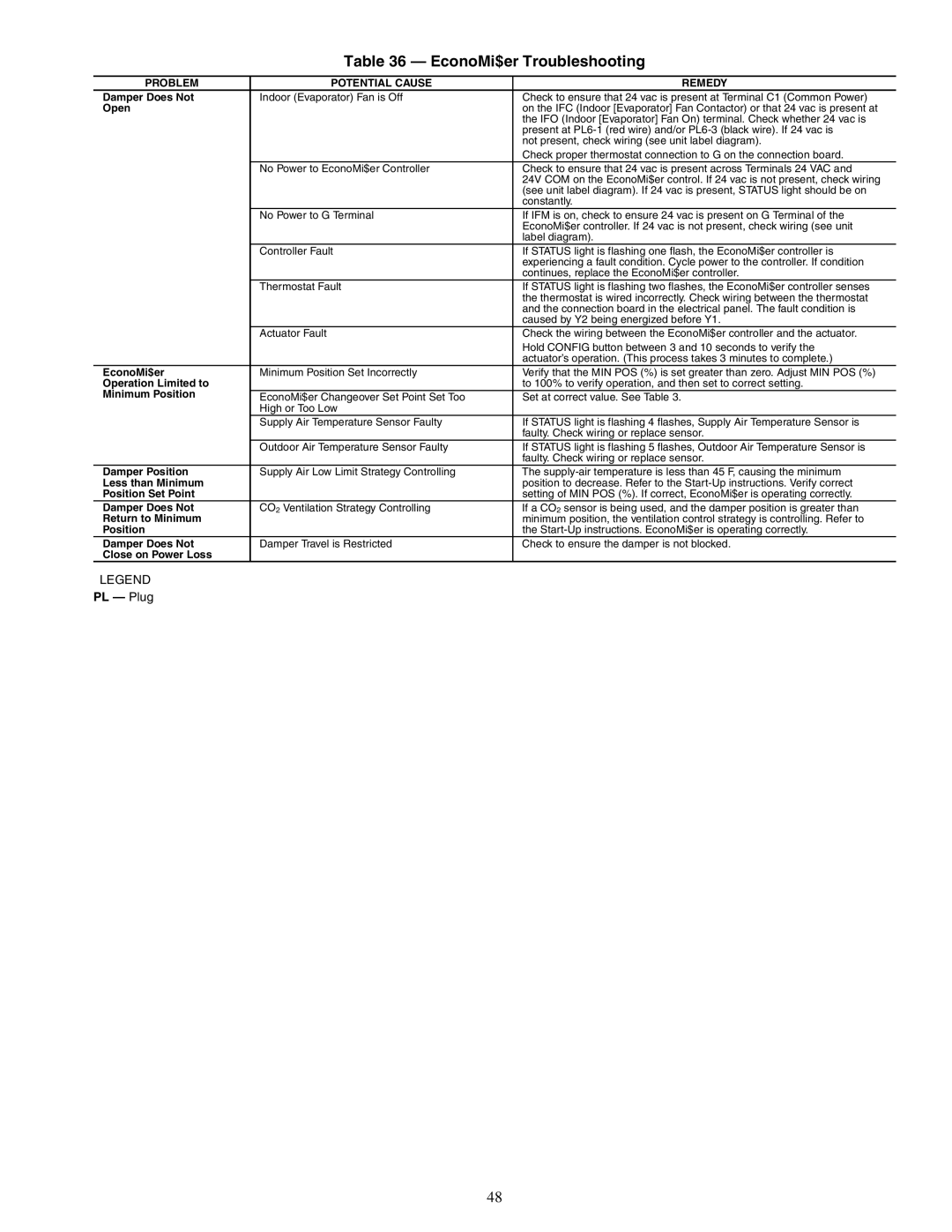
COOLING, UNITS WITH ECONOMI$ER — When the outdoor-air temperature (OAT) is above the ECON SP set point and the room thermostat calls for Stage 1 cooling (R to G + Y1), the indoor (evaporator) fan motor (IFM) is energized and the EconoMi$er damper modulates to minimum position. The compressor contactor is energized to start the compressor and outdoor (condenser) fan motor (OFM). After the thermostat is satisfied, the damper modulates to the fully closed position when the IFM is deenergized.
When the OAT is below the ECON SP setting and the room thermostat calls for Stage 1 cooling (R to G + Y1), the EconoMi$er modulates to the minimum position when the IFM is energized. The EconoMi$er provides Stage 1 of cooling by modulating the return and outdoor air dampers to maintain a 55 F supply air set point. If the supply-air temperature (SAT) is greater than 57 F, the EconoMi$er modulates open, allowing a greater amount of outdoor air to enter the unit. If the SAT drops below 53 F, the outdoor air damper modulates closed to reduce the amount of outdoor air. When the SAT is between 53 and 57 F, the EconoMi$er maintains its position.
If outdoor air alone cannot satisfy the cooling requirements of the conditioned space, and the OAT is above the MECH CLG LOCKOUT set point, the EconoMi$er integrates free cooling with mechanical cooling. This is accomplished by the strategies below.
NOTE: Compressor has a 2-minute Minimum On, Minimum Off, and Interstage delay timer.
1.If Y1 is energized, and the room thermostat calls for Y2 (2-stage thermostat), the compressor and OFM are ener- gized. The EconoMi$er damper is maintained at its cur- rent position.
2.If Y1 is energized for more than 20 minutes, and Y2 is not energized (whether or not a 2-stage thermostat is used), the compressor and OFM are energized. The EconoMi$er damper is maintained at its current position.
3.If Y1 is energized, and the compressor is already ener- gized (see Step 2) and the room thermostat calls for Y2, the compressor continues to operate.
4.If the compressor is energized and the thermostat is satis- fied, the compressor, the OFM, and IFM are deenergized and the EconoMi$er modulates closed.
When the OAT is below the MECH CLG LOCKOUT set point, the compressors remain off.
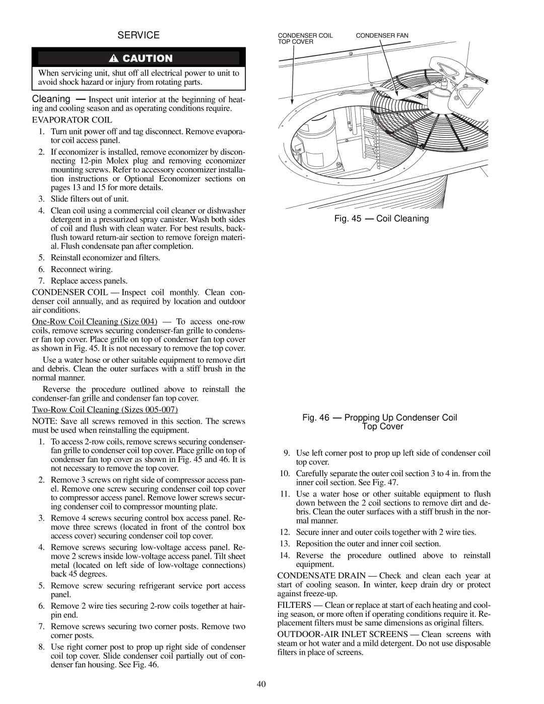
HEATING, UNITS WITH ECONOMI$ER — When the ther- mostat calls for heating, terminal W1 is energized. To prevent thermostat short-cycling, the unit is locked into the Heating mode for at least 1 minute when W1 is energized. The induced- draft motor is energized and the burner ignition sequence be- gins. The indoor (evaporator) fan motor (IFM) is energized 45 seconds after a flame is ignited and the damper moves to the minimum position. On units equipped for two stages of heat, when additional heat is needed, W2 is energized and the high- fire solenoid on the main gas valve (MGV) is energized. When the thermostat is satisfied and W1 is deenergized, the IFM stops after a 45-second time-off delay. The economizer damper then moves to the fully closed position. When using continuous fan, the damper will remain in the minimum position.
