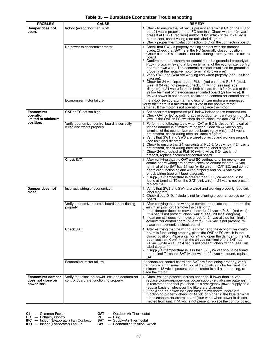
Table 35 — Durablade Economizer Troubleshooting
| PROBLEM |
|
| CAUSE |
| REMEDY | ||
Damper does not |
| Indoor (evaporator) fan is off. | 1. | Check to ensure that 24 vac is present at terminal C1 on the IFC or | ||||
open. |
|
|
|
|
| that 24 vac is present at the IFO terminal. Check whether 24 vac is | ||
|
|
|
|
|
|
|
| present at |
|
|
|
|
|
|
|
| not present, check wiring (see unit label diagram). |
|
|
|
|
|
|
| 2. | Check proper thermostat connection to G on the connection board. |
|
|
|
| No power to economizer motor. | 1. | Check that SW3 is properly making contact with the damper | ||
|
|
|
|
|
|
|
| blade. Check that SW1 is in the NC (normally closed) position. |
|
|
|
|
|
|
| 2. Check diode D18. If diode is not functioning properly, replace control | |
|
|
|
|
|
|
|
| board. |
|
|
|
|
|
|
| 3. | Confirm that the economizer control board is grounded properly at |
|
|
|
|
|
|
|
| |
|
|
|
|
|
|
|
| board (brown wire). The economizer motor must also be grounded |
|
|
|
|
|
|
|
| properly at the negative motor terminal (brown wire). |
|
|
|
|
|
|
| 4. | Verify SW1 and SW3 are working and wired properly (see unit label |
|
|
|
|
|
|
|
| diagram). |
|
|
|
|
|
|
| 5. | Check for 24 vac input at both |
|
|
|
|
|
|
|
| wire). If 24 vac not present, check unit wiring (see unit label |
|
|
|
|
|
|
|
| diagram). If 24 vac is found in both places, check for 24 vac at the |
|
|
|
|
|
|
|
| yellow terminal of the economizer control board (yellow wire). If |
|
|
|
|
|
|
|
| 24 vac power is not present, replace the economizer control board. |
|
|
|
| Economizer motor failure. |
| If the indoor (evaporator) fan and economizer motor are energized, | ||
|
|
|
|
|
|
| verify that there is a minimum of 18 vdc at the positive motor | |
|
|
|
|
|
|
| terminal. If the motor is not operating, replace the motor. | |
Economizer |
| OAT or EC set too high. |
| 1. | Set at correct temperature (3 F below indoor space temperature). | |||
operation |
|
|
|
| 2. | Check OAT or EC by setting above outdoor temperature or humidity | ||
limited to minimum |
|
|
|
|
| level. If the OAT or EC switches do not close, replace OAT or EC. | ||
position. |
|
| Verify economizer control board is correctly | 1. | Perform the following tests when OAT or EC is closed, Y1 is called | |||
|
|
|
| wired and works properly. |
|
| for and damper is at minimum position. Confirm 24 vac on gray | |
|
|
|
|
|
|
|
| terminal of the economizer control board (gray wire). If 24 vac is |
|
|
|
|
|
|
|
| not present, check wiring (see unit label diagram). |
|
|
|
|
|
|
| 2. | Verify that SW1 and SW3 are wired correctly and working properly |
|
|
|
|
|
|
|
| (see unit label diagram). |
|
|
|
|
|
|
| 3. | Check to ensure that 24 vac exists at |
|
|
|
|
|
|
|
| not present, check wiring (see unit wiring label diagram). |
|
|
|
|
|
|
| 4. | Check 24 vac output at |
|
|
|
|
|
|
|
| present, replace economizer control board. |
|
|
|
| Check SAT. |
|
| 1. | After verifying that the OAT and EC settings and the economizer |
|
|
|
|
|
|
|
| control board wiring are correct, check to ensure that the 24 vac |
|
|
|
|
|
|
|
| terminal of the SAT has 24 vac (white wire). If OAT, EC, and control |
|
|
|
|
|
|
|
| board are functioning and wired properly and no 24 vac exists, |
|
|
|
|
|
|
|
| check wiring (see unit label diagram). |
|
|
|
|
|
|
| 2. | If |
|
|
|
|
|
|
|
| found at terminal T2 on the SAT (pink wire). If 24 vac is not present, |
|
|
|
|
|
|
|
| replace SAT. |
Damper does not |
| Incorrect wiring of economizer. | 1. | Verify that SW2 and SW4 are wired and working properly (see unit | ||||
close. |
|
|
|
|
| label diagram). | ||
|
|
|
|
|
|
| 2. Check diode D19. If diode is not functioning properly, replace control | |
|
|
|
|
|
|
|
| board. |
|
|
|
| Verify economizer control board is functioning | 1. | After verifying that the wiring is correct, modulate the damper to the | ||
|
|
|
| properly. |
|
|
| minimum position. Remove the calls for G. |
|
|
|
|
|
|
| 2. | If the damper does not move, check for 24 vac at |
|
|
|
|
|
|
|
| If 24 vac is not present, check wiring (see unit label diagram). |
|
|
|
|
|
|
| 3. | If damper still does not move, check for 24 vac at blue terminal of |
|
|
|
|
|
|
|
| economizer control board (blue wire). If 24 vac is not present, re- |
|
|
|
|
|
|
|
| place the economizer circuit board. |
|
|
|
| Check SAT. |
|
| 1. | After verifying that the wiring is correct and the economizer control |
|
|
|
|
|
|
|
| board is functioning properly, place the OAT or EC switch in the |
|
|
|
|
|
|
|
| closed position. Place a call for Y1 and open the damper to the fully |
|
|
|
|
|
|
|
| open position. Confirm that the 24 vac terminal of the SAT has |
|
|
|
|
|
|
|
| 24 vac (white wire). If 24 vac is not present, check wiring (see unit |
|
|
|
|
|
|
|
| label diagram). |
|
|
|
|
|
|
| 2. | If |
|
|
|
|
|
|
|
| at terminal T1 on the SAT (violet wire). If 24 vac not found, replace |
|
|
|
|
|
|
|
| SAT. |
|
|
|
| Economizer motor failure. |
| If economizer control board and SAT are functioning properly, verify | ||
|
|
|
|
|
|
| that there is a minimum of 18 vdc at the positive motor terminal. If a | |
|
|
|
|
|
|
| minimum if 18 vdc is present and the motor is still not operating, re- | |
|
|
|
|
|
|
| place the motor. | |
Economizer damper |
| Verify that | 1. | Check voltage potential across batteries. If lower than 14 vdc, | ||||
does not close on |
| control board are functioning properly. |
| replace | ||||
power loss. |
|
|
|
|
| is recommended that you check this emergency power supply on a | ||
|
|
|
|
|
|
|
| regular basis or whenever the filters are changed. |
|
|
|
|
|
|
| 2. | If the |
|
|
|
|
|
|
|
| functioning properly, check for 14 vdc or higher at the blue terminal |
|
|
|
|
|
|
|
| of the economizer control board (blue wire) when power is discon- |
|
|
|
|
|
|
|
| nected from unit. If 14 vdc is not present, replace the control board. |
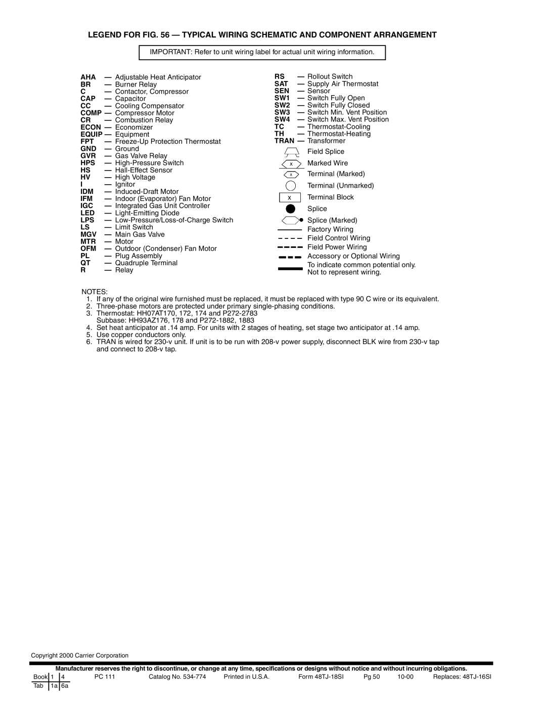
C1 | — Common Power |
| OAT | — | ||||
EC | — Enthalpy Control | PL | — Plug |
|
| |||
IFC | — Indoor (Evaporator) Fan Contactor | SAT | — | |||||
IFO | — Indoor (Evaporator) Fan On | SW | — Economizer Position Switch | |||||
47


