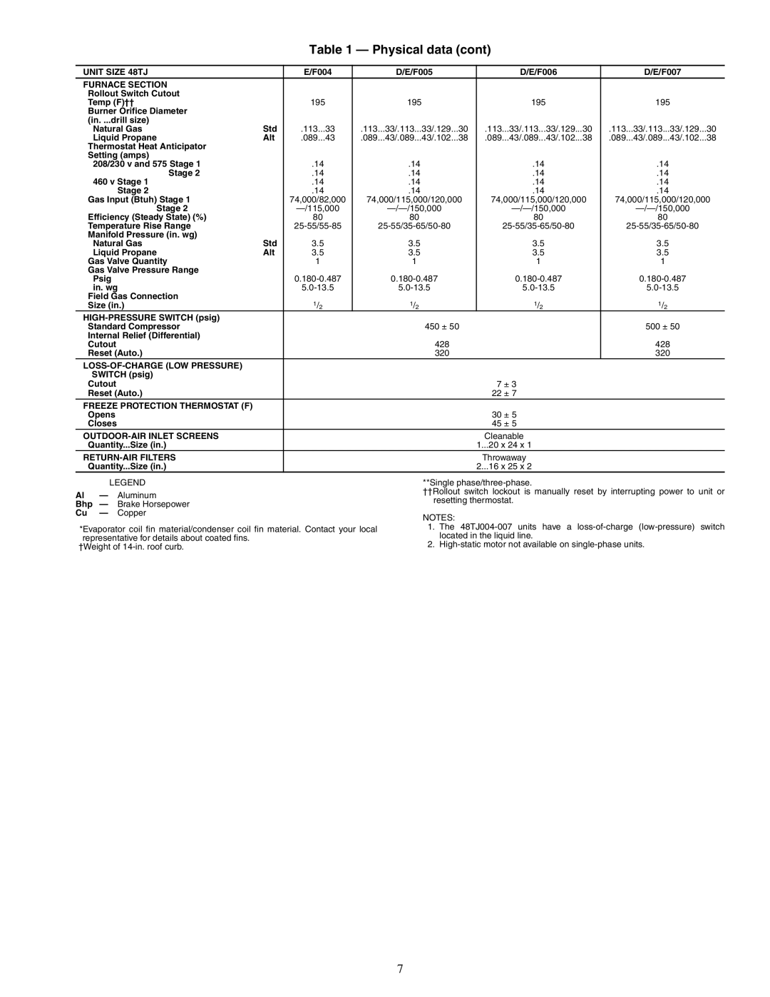
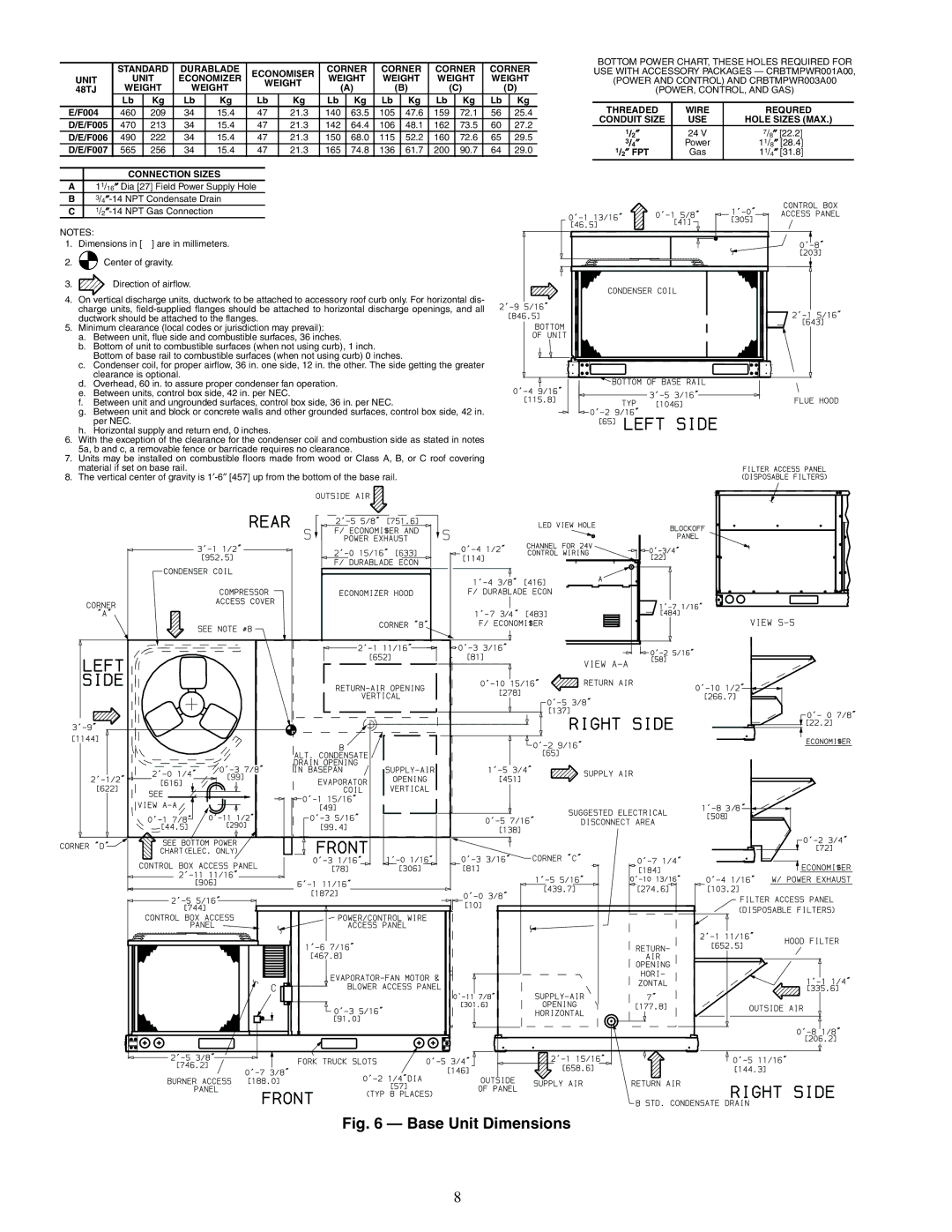
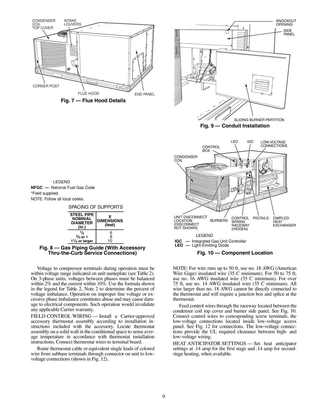
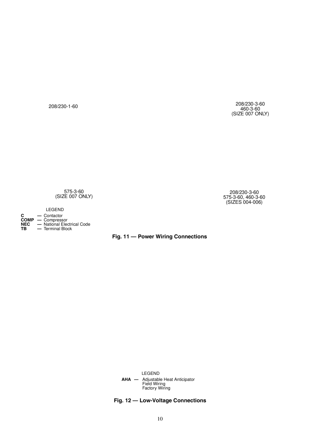
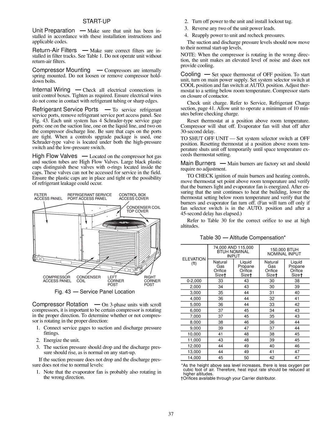
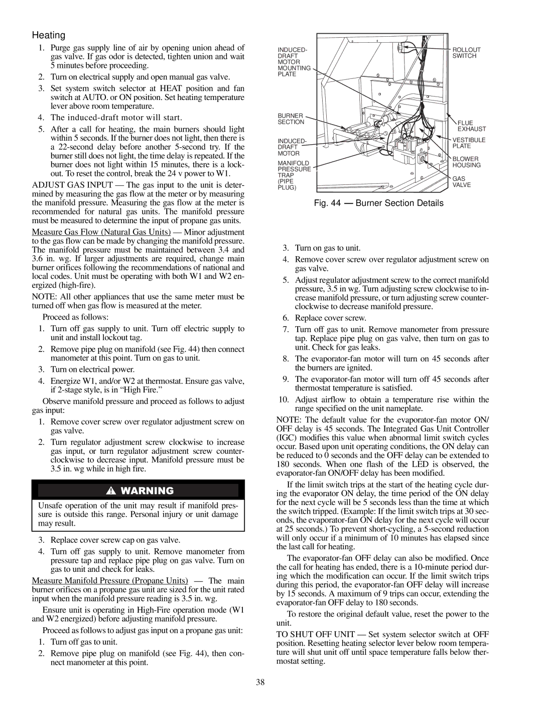
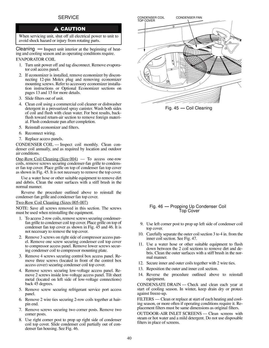
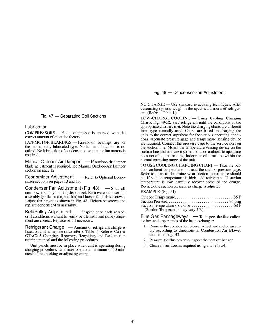
Carrier 48TJD and 48TJE Product Data, Power Exhaust, and Wiring Diagrams

Page 18

TO FUSED

DISCONNECT

CAPACITOR 2

FAN 1

FAN 2


CAPACITOR 1


HT01AH859 (575 VAC)

REDGRAY

H1H2

X4 X2 X3 X1

SECONDARY

230VAC

HT01AH850 (460 VAC)

RED YEL BLU GRAY

H1 H3 H2 H4

X4 X2 X3 X1

SECONDARY

230VAC

RELAY 2

RELAY 1

4-PIN

3-PIN

CONNECTOR PLUG

CONNECTOR PLUG

(HIGH VOLTAGE)

(LOW VOLTAGE)

FIELD SUPPLIED

WIRING

BLACK

BLACK

OR


COMPRESSOR 1


CONTACTOR


11

21


230VAC


13

23


4-PIN


2 x 4 IN.


CONNECTOR


HANDY BOX


PLUG


BLACK

L1

1

1

L1


L2


BLUE

L2 2

2


GREEN GND 3

3

GND

BLACK


4

4


BLUE


230 VAC

GREEN


1 PHASE


LT. BLUE


3

6

9

B


BROWN

FAN 1

BLACK


R1


2

5

8

3-PIN


C1


24 VAC


CONNECTOR

GREEN/


PLUG


YELLOW

1

4

7

A


BLUE


ORANGE

1


YELLOW

2


BROWN

3


BLACK


LT. BLUE


3

6

9

B


BROWN

FAN 2

BLACK


R2


2

5

8

24 VAC


C1


GREEN/


YELLOW

1

4

7

A


BLUE


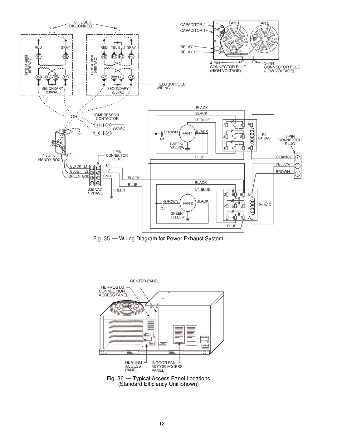
Fig. 35 — Wiring Diagram for Power Exhaust System

CENTER PANEL

THERMOSTAT

CONNECTION

ACCESS PANEL

HEATING

INDOOR FAN

ACCESS

MOTOR ACCESS

PANEL

PANEL

Fig. 36 — Typical Access Panel Locations

(Standard Efficiency Unit Shown)

18
Image 18
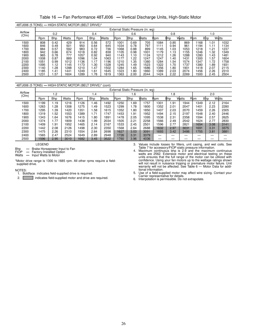
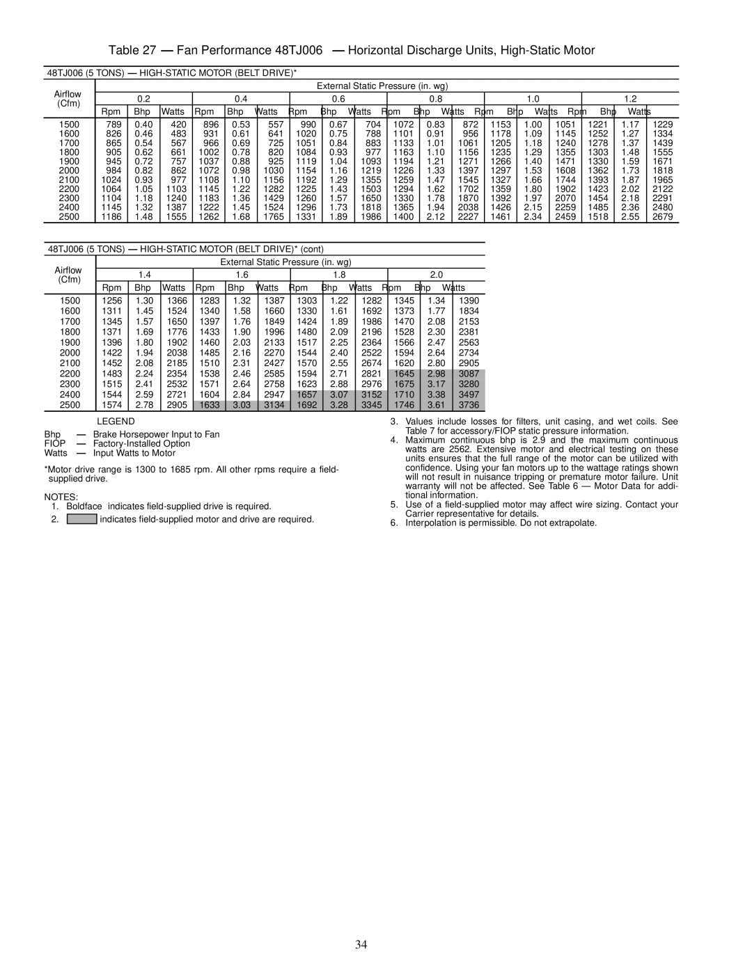
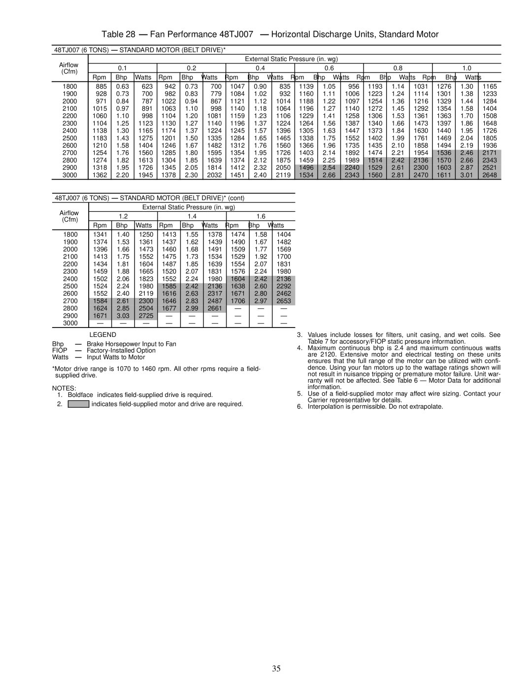
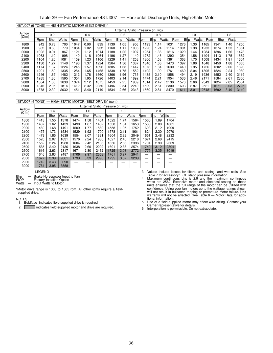
Contents Installation, Start-Up Service Instructions Horizontal Conversion Panels Viewed from Duct End Roof Curb Dimensions Unit Leveling Tolerances Make Electrical Connections Physical Data Unit Size 48TJLOSS-OF-CHARGE LOW Pressure Base Unit Dimensions Conduit Installation Flue Hood DetailsPower Wiring Connections Type FLA Electrical DataSupply Size RLA LRAMake Outdoor-Air Adjustments and Install Outdoor-Air Hood Typical Access Panel Locations Enthalpy Control Installation Horizontal Discharge Block-Off PlateWiring Connections for Outdoor-Air Thermostat Outdoor-Air Hood Assembly EconoMi$er Wiring Wiring Diagram for Power Exhaust System Default Potentiometer Settings Changeover Set PointsBelt Drive Motor Mounting Fan Rpm at Motor Pulley Settings Accessory/FIOP Static Pressure* in. wg 48TJ004-007Motor Data 48TJ004 3 Tons Standard Motor Direct Drive 48TJ004 3 Tons Alternate Motor Belt Drive48TJ004 3 Tons HIGH-STATIC Motor Belt Drive 48TJ005 4 Tons Standard Motor Direct Drive48TJ005 4 Tons Alternate Motor Belt Drive 48TJ006 5 Tons Standard Motor Direct Drive 48TJ006 5 Tons Alternate Motor Belt Drive48TJ006 5 Tons HIGH-STATIC Motor Belt Drive 48TJ007 6 Tons Standard Motor Belt Drive 48TJ007 6 Tons HIGH-STATIC Motor Belt Drive 189 109149 2291005 10281064 9381700 750 473 806 536 48TJ005 4 Tons Alternate Motor Belt Drive817 1900 826 63048TJ005 4 Tons HIGH-STATIC Motor Belt Drive 1800 852 578 1600 770 420 826 4831700 811 494 865 567 1900 894 5671252 12211600 826 483 931 641 1020 788 1101 956 1178 1700 865 567 966 725 1051 883 1133 1061 1205971 787 1022 867 885 623 942 700928 700 982 779 1015 891 1063 9982100 1063 998 1140 1064 1196 1272 1292 1900 982 779 1084 932 1160 1006 1223 11142000 1022 867 1121 1014 1188 1097 1254 1216 2200 1104 1081 1159 1106 1229 1258Altitude Compensation ElevationGas Propane Orifice Size† 000 Heating Page Service Lubrication Cooling Charging Chart, 48TJ004 LED Error Code Description Flash†Flashes Burner Tray Details Symptom Cause Remedy LED Error Code Service AnalysisHeating Service Analysis Problem Cause RemedyCooling Service Analysis Compressor operates continuouslyDurablade Economizer Troubleshooting Damper does notEconoMi$er Troubleshooting Problem Potential Cause RemedyTypical Wiring Diagram and Component Arrangement Switch Max. Vent Position SW4Page START-UP Checklist