Removing the LCD Module
1.Perform the “Removing the Lower Case” procedure described on page
2.Perform the “Removing the Battery Pack” procedure described on page
3.Perform the “Removing the Left and Right Speakers” procedure described on page
4.Perform the “Removing the WLAN Module” procedure described on page
5.Perform the “Removing the
6.Perform the “Removing the HDD Module” procedure described on page
7.Perform the “Removing the Card Reader Board” procedure described on page
8.Perform the “Removing the Mainboard” procedure described on page
9.Perform the “Removing the Keyboard” procedure described on page
10.Perform the “Removing the Power Button Board” procedure described on page
11.Perform the “Removing the Middle Cover Assembly” procedure described on page
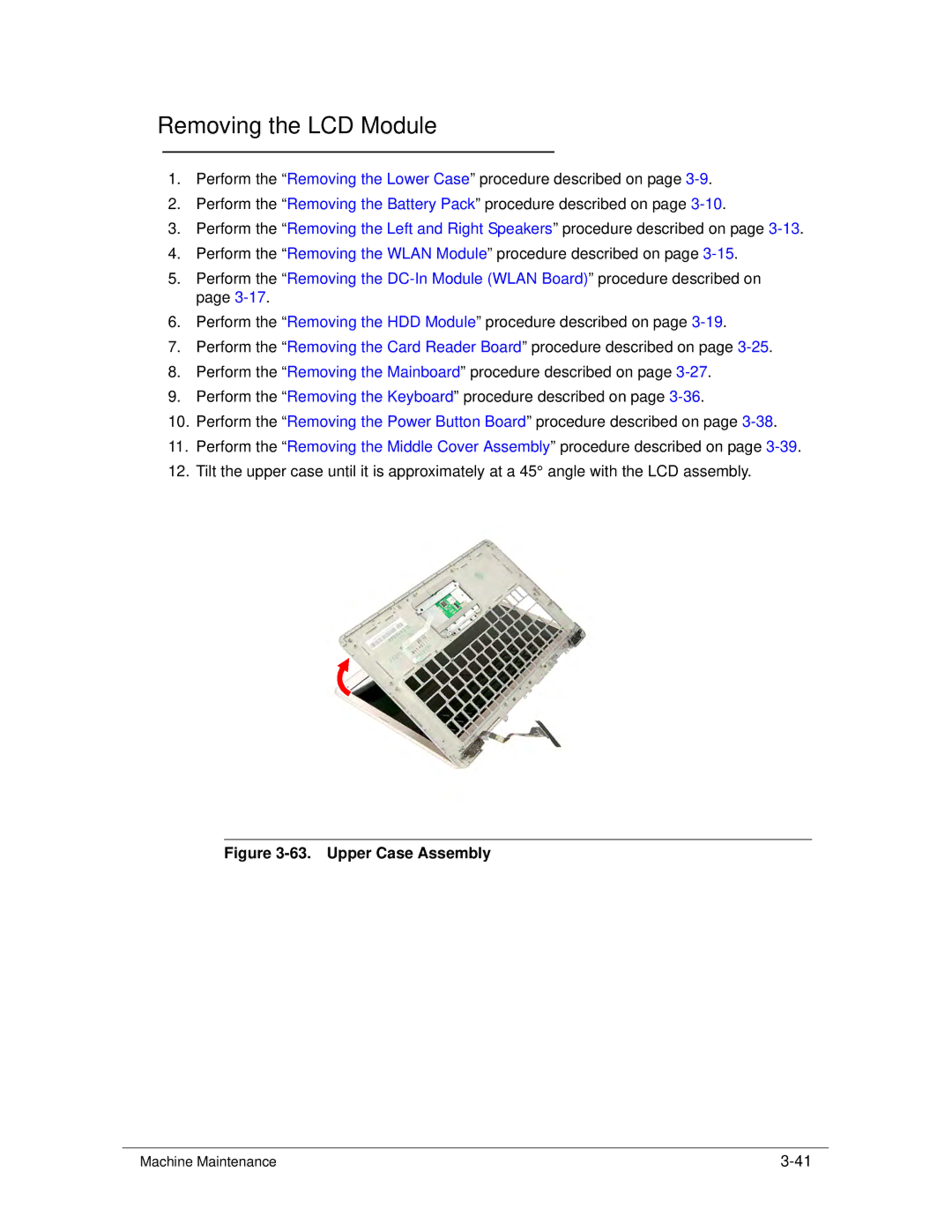
12.Tilt the upper case until it is approximately at a 45° angle with the LCD assembly.
Figure 3-63. Upper Case Assembly
Machine Maintenance |