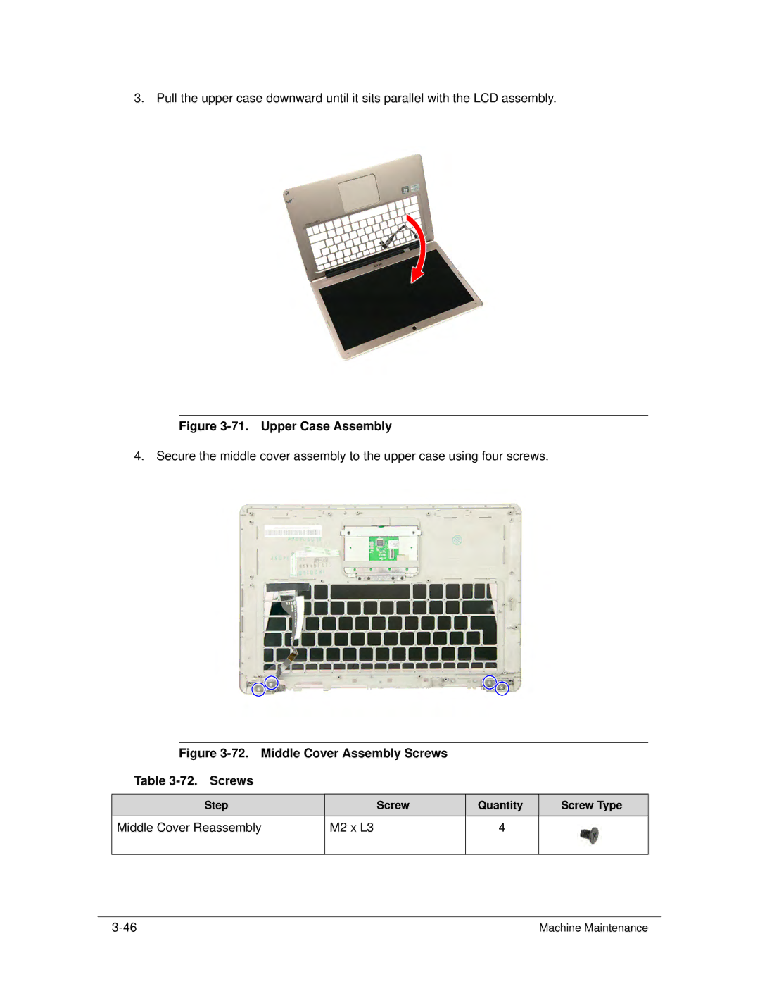
3. Pull the upper case downward until it sits parallel with the LCD assembly.
Figure 3-71. Upper Case Assembly
4. Secure the middle cover assembly to the upper case using four screws.
Figure 3-72. Middle Cover Assembly Screws
Table 3-72. Screws
Step |
| Screw | Quantity | Screw Type |
Middle Cover Reassembly | M2 x L3 |
| 4 |
|
|
|
|
|
|
Machine Maintenance |
