9640A Professional Enhanced Scan Tool
Scan Tool Information
Safety Table of Contents
Page
Safety Precautions
Safety
Risk of explosion
Battery acid is a highly corrosive sulfuric acid
Risk of electric shock
Risk of poisoning
Risk of flying particles
Risk of burns
Risk of injury
Risk of unexpected vehicle movement
Risk of equipment or circuit damage
Table of Contents
Print Data
GM Historic OBD I Diagnostics
GM Enhanced OBD II Diagnostics
Code Lookup
Ford Enhanced OBD II Diagnostics
Ford Historic Self-Test Routines
Iii
Battery Replacement -3Tool Self-Tests
Program Mode -6 Technical Support
Display Test Keyboard Test Memory Test Printer Test
Equipment Tips and Lists
Safety Messages
Check Note
Equipment Damage
Questions and Responses
Manual References
Screens
Vehicle Service Information
Introduction to ON-BOARD Diagnostics
GM On-Board Diagnostics
Ford On-Board Diagnostics
Chrysler On-Board Diagnostics
Diagnostic Link Connectors DLC
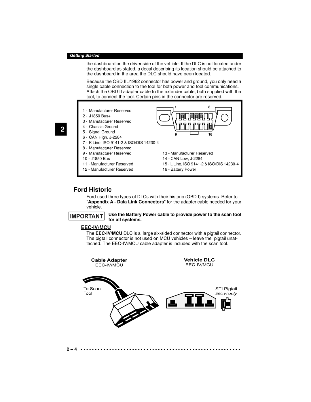
OBD II J1962
Ford Historic
EEC-IV/MCU
Mecs
Pin Mecs
GM Historic
Mecs Ford Probe
Aldl DLCs are usually located under
Diagnostic Trouble Codes Dtcs
Chrysler Historic
SCI serial communications interface DLC is a
P00FF
12V Power Jack
Battery compartment cover
Scan Tool
Display
Specifications
Accessories
Keyboard
Internal Batteries
Power
AC Power Adapter
Key turns on
Scan Tool Setup
Cabling
Seiko DPU-414 Kodak Diconix 180si serial printer model
Panasonic KX-P1131 printer
Printer end
Ascii character set
Menu New printer settings Are tested by printing
Use Key to Return to the previous
Press to continue
Connecting the Scan Tool
Refer to Diagnostic Link Connectors DLC
Vehicle Selection
Changing the Vehicle
Viewing Data
User Interface
User Responses
Entire Data List
View Data Setup
Custom Data List
Manual Info
Readiness
Abbreviated Name Expanded Name
He Obdii Fu Ction List
Read Codes
Function List menu and press
To the Obdii Function List
OBD II Function List
Pending Codes
Erase Codes
To the Obdii Function List. If any
Return to the Obdii Function List
View Data
List
Obdii Function
Responding.Continue
View Freeze Data
Select View Freeze Data from
Obdii Function List and press
Select the desired test from the menu
O2 Monitor Test
SelectO2MonitorTest from the Obdii
Press Grouping O2 sen
NON-CONTINUOUS Tests
ON-BOARD Systems
Select Non-Contin Tests from Obdii Function List and press
Record Data
Select On-Board Systems from Obdii Function List and press
Select Record Data from the Obdii Function List and press
Obdii Function List
Vehicle Info
If Trigger On Codes was selected
Function List
Review Data
Select Vehicle Info from the Obdii Function List and press
Select Review Data from the Obdii
Playback
Datack
Interface on page 3-4 of Using
Print Data
Printing Data except Playback
Scroll
Printing Playback Data
Start Frame screen
Printout of the recording might
Code Lookup
Lookup from the Obdii Function List
Read Codes
GM Historic OBD I Diagnostics
Manual Info
SelectReadCodes from the GM Func Tion List and press
Erase Codes
View Data
Record Data
SelectRecordData from the GM Func Tion List and press
Review Data
Data
Return to the GM Function List
Field Service
SelectPlayback from the Review Data
Data on
Mode. It is possible to have the Field Service mode funct
While in FieldService mode, no new trouble cod Cle’s memory
Code 12 will look like
Code Lookup
Print Data
Code 23 will look like
GM Enhanced OBD II Diagnostics
Readiness
Nostics
Pending Codes
Pending Cod s on page 4-3 of Global OBD II Diagnostics
Erase On page 4-3 of Global OBD II Diagnostics
To the GM Function List
Select View Data from theGM Func Tion List and press
Non-Continuous Tests
View Freeze Data
O2 Monitor Test
On-Board Systems
Vehicle Info
M Readiness O2 Monitor Test DTC Codes
Pending Codes Playback Freeze Frame Vehicle Info
GM Enhanced OBD II Diagnostics
Ford Historic SELF-TEST Routines
Read Koeo Codes
Select Read Koeo Codes from Ford Function List and press
Select FastCodes orSlow Codes and press
Avoid Cooling Fan! It May Turn On During Test
Read Koer Codes
Ford Function List
SelectFastCodes orSlowCodes
Ford Function List screen
Review Codes
Elect Review Codes from the Ford Function List and press
Tion List or To the Review Codes
Follow all instructions on the display
Select Erase Codes from the Ford
Press After each message
Tion Li t
Fo d Function List
Never Lay To ls On Vehicle Battery. Tools May Create
Wiggle Te t EEC-IV Vehicles
Wiggle Test, oft
Output Switch Test EEC-IV Vehicles
Select Output Sw Test from the Ford Function List and press
Cylinder Cyl Balance Test EEC-IV Vehicles
Remaining=156
Exhaust gases are harmful Thal. Always op rate vehi
Return to the Ford Function List
Select IVSC-Speed Ctrl from the Ford
IVSC-Speed Ctrl EEC-IV Vehicles
Reading Ivsc Koeo Codes
Avoid Cooling Fan! It May Turn On During
Reading Ivsc Koer Codes
Star Test Mode EEC-IV, Mecs and MCU Vehi l s
Not over-rev engine. Observe all safety precautions
Exhaust gases are harmful or lethal. Always operate vehi
Three-Digit DTC 214 will Flash as follows
Two-Digit DTCs 12, 42 will Flash as follows
Code Lookup
Print Data
Return to the Ford Function List menu
Record Data
DCL Data Functions EEC-IV Vehicles
View Data
Data from the Ford Function List
Playback Data
Assist with the operation of the to l
Goes to the Select Data to View screen
Ta r
Recorded data
Ta List header th
Playback Use
Readiness
Ford Enhanced OBD II Diagnostics
Manual Info
Read MIL DTC
Erase Codes
Read All DTC
Pending Codes
View Data
View Freeze Data
Three Quick Tests are performed on all Ford vehicles
Quick Tests
Koeo On Demand
Time Remaining will be displayed
Key to return to Press
Reference
Select Koer On Demand from
Unc i n List or
Quick Tests screen
Select Koeo Output State from
Vehicle in a well-ventilated ar a
Quick Tests 7.3L Powerstroke Diesel Only
SelectKOEOInj.Buzz from the Quick
Ford Function List or
Do not over-rev engine. Observe all saf ty precautions
To begin Scan tool
Select Koer Switch from the Quick
Tests
Follow all user interaction required to run Self-Test
Non-Contin Tests
Ford Enhanced OBD II Diagnostics
SelectReadCodes from the Chrysler
Manual Info
Read Codes
Keep hands and Tools away from fan and ngine uring Test
There may be times wh re
Use Arrow keys to scroll
Circuit Disconnected
Actuator Te the co Es and pr ss Malfunction
Functions list
He Chrysler F Nc ons li t
Select View Data from the Chrysler
View Data
Chrysler Functions menu
Scan Tool
Neveroperate the tool while driving. Have no her person
Using The Scan Tool for Entire
Select Record Data from the Chrysler
Refer to ViewingData on page 3-9
Switch Test
Actuator Test
Some Actuator Tests may activate the fuel pump. Do not
Idle Speed Test
Tions list
Reset EMR Lamp
Controller Info
Select Controller Info from
SET Basic Time
To the Chrysler Functions list
He R view
Codes, Temp Codes and Controller
Pl yb ck is
Playback
On page 4-12 of Global OBD II Diagnostics
Tions are available
Play with the definition when applicable
Key Play if the DTC type does not exist
Vehicle, then a message displays Press
Chrysler Diagnostics
Review the Safety Precautions before troubleshooting
HOW to USE ON-LINE Help
Using Non-OBD II Adapter Cables
Check the following
Error Messages
Vehicle Communication Fault
Operating Error or Erroneous Data
Follow these steps to replace the batteries
Battery Replacement
Check the following if an error message displays
Polarity
From the Tool Self Est m
Tool SELF-TESTS
Display Test
Tool Self-Te t me
Printer Test
Interface on page 3-4 of Using
Memory Test
Lf-Test m nu
Program Mode
He Sc Tool
Abcdefghijklmno
Appendix a Data Link Connectors
GM Cars, Light Trucks & Vans
Series
Series 4x4, Small Van
Ford, Lincoln & Mercury Cars, Light Trucks & Vans
Mecs 6-Pin DLC Mecs 17-Pin DLC
OBD II J1962 DLC
SHP
GVW
Chrysler Cars, Light Trucks & Vans
Chrysler Cars, Light Trucks & Vans
Smec
Data Link Connectors
AC Pressure Sensor
AC Pressure Switch
AC Clutch Relay
Actuator
Boost Control Solenoid
Brake Switch Signal
Data Link Connector DLC
Closed Loop CL
Detonation
Duty Cycle
Hall Effect Sensor
Freeze Frame
Ground GND
Knock Sensor KS
NOx
Monitor
Mpfi or MFI
O2S
Relay
Open Loop OL
Purge Solenoid
Reluctance Sensor
Torque Converter Clutch
SFI or Sefi
Solenoid
Transmission Control Module
Throttle Body
Transmission Fluid Temperature Sensor
Transmission Fluid Pressure
Vehicle Theft Deterrent
Glossary