Front Panel | |
|
|
FRONT PANEL
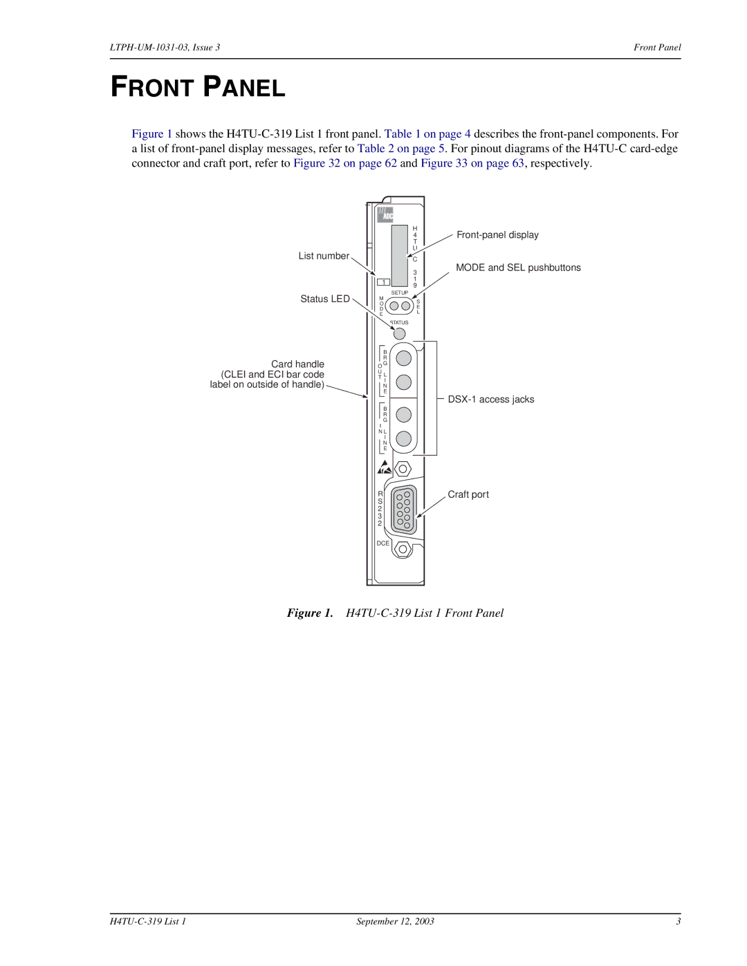
Figure 1 shows the H4TU-C-319 List 1 front panel. Table 1 on page 4 describes the front-panel components. For a list of front-panel display messages, refer to Table 2 on page 5. For pinout diagrams of the H4TU-C card-edge connector and craft port, refer to Figure 32 on page 62 and Figure 33 on page 63, respectively.
List number
1
Status LED |
| M | |
|
| O | |
|
| D | |
|
| E | |
|
|
|
|
|
| B | |
Card handle |
| R | |
O G | |||
(CLEI and ECI bar code | U | ||
T L | |||
label on outside of handle) |
| I | |
| N | ||
|
| E | |
|
|
|
|
|
|
|
|
|
| B | |
|
| R | |
|
| G | |
|
| I | |
| N L | ||
|
| I | |
|
| N | |
|
| E | |
|
|
|
|
H
4 T U
*
C
3
1
9
SETUP
S
E
L
STATUS
MODE and SEL pushbuttons
RCraft port
S 2 3 2
DCE
Figure 1. H4TU-C-319 List 1 Front Panel
September 12, 2003 | 3 |