Appendix A - Specifications | |
|
|
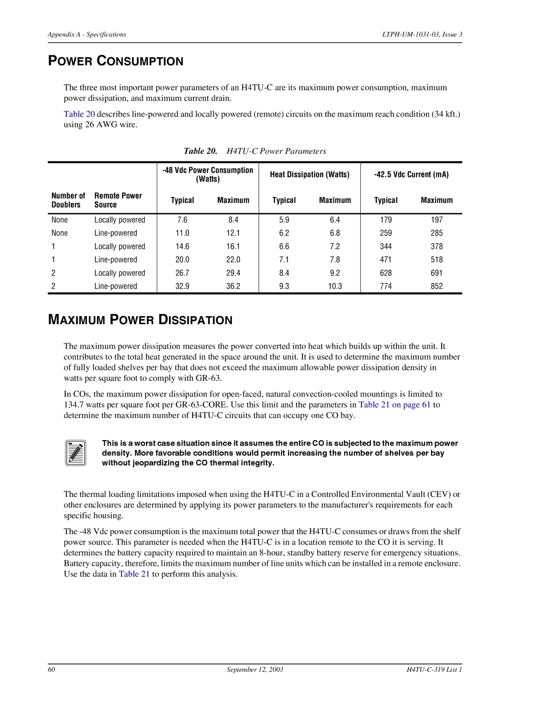
POWER CONSUMPTION
The three most important power parameters of an
Table 20 describes
Table 20. H4TU-C Power Parameters
|
| Heat Dissipation (Watts) | ||||||
|
|
| (Watts) | |||||
|
|
|
|
|
|
| ||
Number of | Remote Power | Typical | Maximum | Typical | Maximum | Typical | Maximum | |
Doublers | Source | |||||||
|
|
|
|
|
| |||
|
|
|
|
|
|
|
| |
None | Locally powered | 7.6 | 8.4 | 5.9 | 6.4 | 179 | 197 | |
None | 11.0 | 12.1 | 6.2 | 6.8 | 259 | 285 | ||
1 | Locally powered | 14.6 | 16.1 | 6.6 | 7.2 | 344 | 378 | |
1 | 20.0 | 22.0 | 7.1 | 7.8 | 471 | 518 | ||
2 | Locally powered | 26.7 | 29.4 | 8.4 | 9.2 | 628 | 691 | |
2 | 32.9 | 36.2 | 9.3 | 10.3 | 774 | 852 | ||
|
|
|
|
|
|
|
| |
MAXIMUM POWER DISSIPATION
The maximum power dissipation measures the power converted into heat which builds up within the unit. It contributes to the total heat generated in the space around the unit. It is used to determine the maximum number of fully loaded shelves per bay that does not exceed the maximum allowable power dissipation density in watts per square foot to comply with
In COs, the maximum power dissipation for
134.7watts per square foot per
This is a worst case situation since it assumes the entire CO is subjected to the maximum power density. More favorable conditions would permit increasing the number of shelves per bay without jeopardizing the CO thermal integrity.
The thermal loading limitations imposed when using the
The
60 | September 12, 2003 |