Front PanelLTPH-UM-1031-03, Issue 3
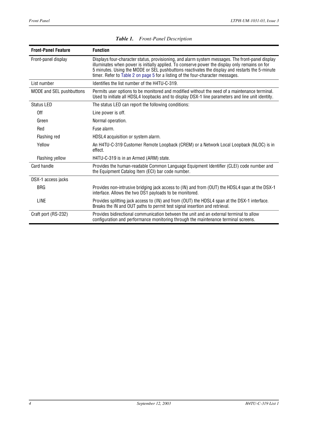
| Table 1. |
|
|
| Function |
|
|
| Displays |
| illuminates when power is initially applied. To conserve power the display only remains on for |
| 5 minutes. Using the MODE or SEL pushbuttons reactivates the display and restarts the |
| timer. Refer to Table 2 on page 5 for a listing of the |
|
|
List number | Identifies the list number of the |
|
|
MODE and SEL pushbuttons | Permits user options to be monitored and modified without the need of a maintenance terminal. |
| Used to initiate all HDSL4 loopbacks and to display |
|
|
Status LED | The status LED can report the following conditions: |
Off | Line power is off. |
Green | Normal operation. |
Red | Fuse alarm. |
Flashing red | HDSL4 acquisition or system alarm. |
Yellow | An |
| effect. |
Flashing yellow | |
|
|
Card handle | Provides the |
| the Equipment Catalog Item (ECI) bar code number. |
|
|
| |
BRG | Provides |
| interface. Allows the two DS1 payloads to be monitored. |
LINE | Provides splitting jack access to (IN) and from (OUT) the HDSL4 span at the |
| Breaks the IN and OUT paths to permit test signal insertion and retrieval. |
Craft port (RS-232)
Provides bidirectional communication between the unit and an external terminal to allow configuration and performance monitoring through the maintenance terminal screens.
4 | September 12, 2003 |