Procedure
To install an
1.Choose an Installation that is a suitable place on the network to install the Wireless Router. Ensure the Wireless Router and the DSL/Cable modem are powered OFF.
Note
For best Wireless reception and performance, the Wireless Router should be positioned in a central location with minimum obstructions between the Wireless Router and the PCs.
Also, if using multiple Access Points, adjacent Access Points should use different Channels with at least a 2 channel separation.
2.Connect LAN Cables using standard LAN cables to connect PCs to the Switching Hub ports on the Wireless Router. Both
If required, connect any port to a normal port on another Hub, using a standard LAN cable. Any LAN port on the Wireless Router will automatically function as an “Uplink” port when required.
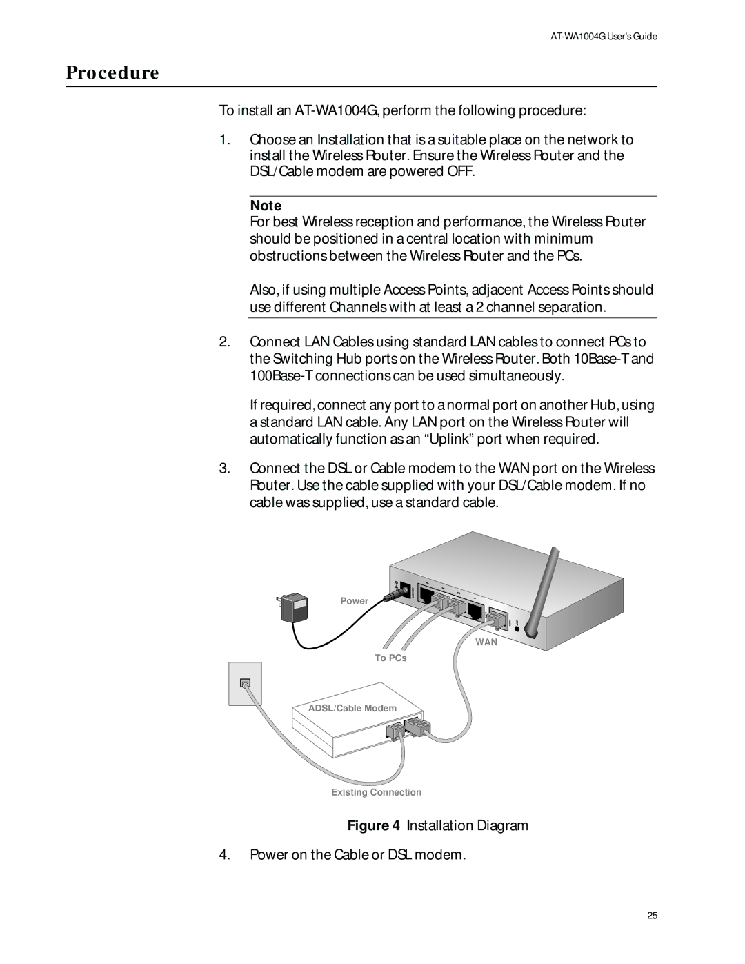
3.Connect the DSL or Cable modem to the WAN port on the Wireless Router. Use the cable supplied with your DSL/Cable modem. If no cable was supplied, use a standard cable.
Power
![]() POWER
POWER
LAN |
|
WAN | INIT |
WAN
To PCs
ADSL/Cable Modem
Existing Connection
Figure 4 Installation Diagram
4.Power on the Cable or DSL modem.
25