External Connection
Connecting the UPS
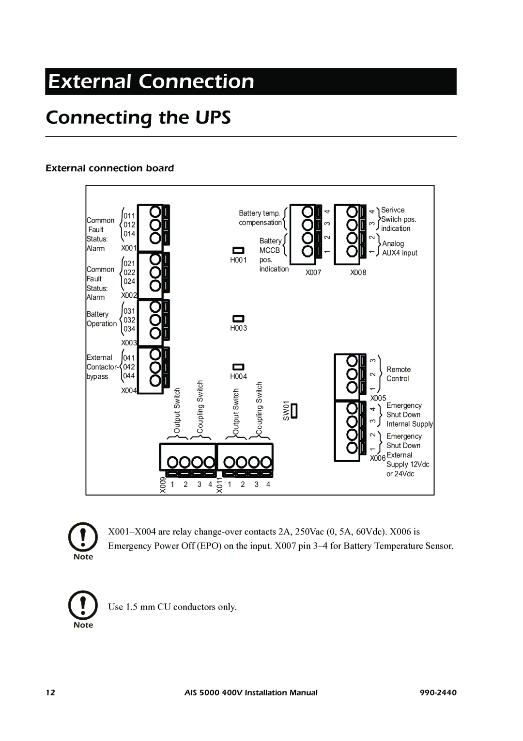
External connection board
| 011 |
|
|
|
|
|
| Battery temp. |
| 4 | 4 | Serivce | ||
Common |
|
|
|
|
|
|
|
|
| Switch pos. | ||||
|
|
|
|
|
| compensation |
| 3 | 3 | |||||
012 |
|
|
|
|
|
|
| |||||||
Fault |
|
|
|
|
|
|
| indication | ||||||
|
|
|
|
|
|
|
|
|
|
|
| |||
014 |
|
|
|
|
|
|
|
|
|
| 2 | 2 | ||
Status: |
|
|
|
|
|
|
|
| Battery |
|
| |||
|
|
|
|
|
|
|
|
|
| Analog | ||||
X001 |
|
|
|
|
|
|
|
|
|
|
| |||
Alarm |
|
|
|
|
|
|
|
| MCCB |
|
|
| ||
|
|
|
|
|
|
|
|
| 1 | 1 | AUX4 input | |||
|
|
|
|
|
|
| H001 |
| pos. |
|
|
| ||
| 021 |
|
|
|
|
|
|
|
|
|
| |||
Common |
|
|
|
|
|
|
|
| indication |
|
|
| ||
022 |
|
|
|
|
|
|
|
| X007 | X008 |
| |||
Fault |
|
|
|
|
|
|
|
|
|
|
| |||
024 |
|
|
|
|
|
|
|
|
|
|
|
|
| |
Status: |
|
|
|
|
|
|
|
|
|
|
|
|
| |
X002 |
|
|
|
|
|
|
|
|
|
|
|
|
| |
Alarm |
|
|
|
|
|
|
|
|
|
|
|
|
| |
Battery | 031 |
|
|
|
|
|
|
|
|
|
|
|
|
|
032 |
|
|
|
|
|
|
|
|
|
|
|
|
| |
Operation |
|
|
|
|
| H003 |
|
|
|
|
|
| ||
| 034 |
|
|
|
|
|
|
|
|
|
|
| ||
| X003 |
|
|
|
|
|
|
|
|
|
|
|
|
|
External | 041 |
|
|
|
|
|
|
|
|
|
|
| 3 |
|
Contactor- | 042 |
|
|
|
|
|
|
|
|
|
|
| 2 | Remote |
bypass | 044 |
|
|
|
|
| H004 |
|
|
|
| |||
|
|
|
|
|
|
|
|
| Control | |||||
|
| Coupling Switch |
|
| Coupling Switch |
|
|
| ||||||
|
|
|
|
|
|
|
|
|
|
| ||||
| X004 | Output Switch |
|
|
|
| Output Switch |
|
| 1 |
| |||
|
|
|
|
|
|
| X005 | |||||||
|
|
|
|
|
| SW01 |
| |||||||
|
|
|
|
|
|
| 2 3 4 | Emergency | ||||||
|
|
|
|
|
|
| Shut Down | |||||||
|
|
|
|
|
|
| Internal Supply | |||||||
|
|
|
|
|
|
| Emergency | |||||||
|
|
|
|
|
|
|
|
|
|
|
|
|
| |
|
|
|
|
|
|
|
|
|
|
|
|
| 1 | Shut Down |
|
|
|
|
|
|
|
|
|
|
|
|
|
| |
|
|
|
|
|
|
|
|
|
|
|
|
| X006External | |
|
|
|
|
|
|
|
|
|
|
|
|
|
| Supply 12Vdc |
| X009 |
|
|
|
| X011 |
|
|
|
|
|
|
| or 24Vdc |
| 1 | 2 | 3 | 4 | 1 | 2 | 3 | 4 |
|
|
|
| ||
|
|
|
|
|
|
|
|
|
|
|
|
| ||
Note
Use 1.5 mm CU conductors only.
Note
12 | AIS 5000 400V Installation Manual |