Relay Board
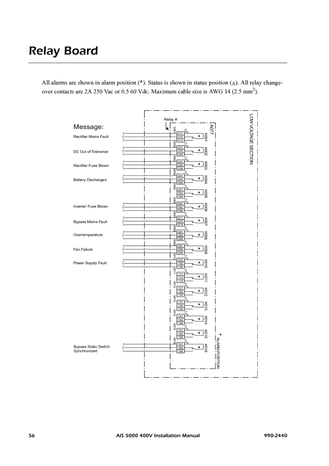
All alarms are shown in alarm position (*). Status is shown in status position (∆ ). All relay change- over contacts are 2A 250 Vac or 0.5 60 Vdc. Maximum cable size is AWG 14 (2.5 mm2).
Message:
Rectifier Mains Fault
DC Out of Tolerance
Rectifier Fuse Blown
Battery Discharged
Inverter Fuse Blown
Bypass Mains Fault
Overtemperature
Fan Failure
Power Supply Fault
Bypass Static Switch Synchronized
Relay #
X001 |
| 2,5 |
| ||
|
| 011 |
|
|
|
|
| 012 |
|
|
|
|
| 013 |
|
|
|
X002 | 2,5 |
| |||
|
| ||||
|
| 021 |
|
|
|
|
| 022 |
|
|
|
|
| 024 |
|
|
|
X003 | 2,5 |
| |||
|
| ||||
|
| 031 |
|
|
|
|
| 032 |
|
|
|
|
| 034 |
|
|
|
X004 | 2,5 |
| |||
|
| ||||
|
| 041 |
|
|
|
|
| 042 |
|
|
|
|
|
|
|
| |
|
| 044 |
|
|
|
X005 | 2,5 |
| |||
|
| ||||
051 |
| ||||
|
|
|
|
| |
|
| 052 |
|
|
|
X006 | 054 | 2,5 |
| ||
|
| ||||
|
| 061 |
|
|
|
|
| 062 |
|
|
|
|
| 064 |
|
|
|
X007 | 2,5 |
| |||
|
| ||||
|
| 071 |
|
|
|
|
| 072 |
|
|
|
|
| 074 |
|
|
|
X008 | 2,5 |
| |||
|
| ||||
|
| 081 |
|
|
|
|
| 082 |
|
|
|
|
| 084 |
|
|
|
X009 | 2,5 |
| |||
|
| ||||
|
| 091 |
|
|
|
|
| 092 |
|
|
|
|
| 094 |
|
|
|
X010 | 2,5 |
| |||
|
| ||||
|
| 101 |
|
|
|
|
| 102 |
|
|
|
|
| 104 |
|
|
|
X011 | 2,5 |
| |||
|
| ||||
111 |
| ||||
|
|
|
|
| |
|
| 112 |
|
|
|
X012 | 114 |
|
|
| |
2,5 |
| ||||
|
| ||||
|
| 121 |
|
|
|
|
| 122 |
|
|
|
X013 | 124 |
|
|
| |
2,5 |
| ||||
|
| ||||
|
| 131 |
|
|
|
|
| 132 |
|
|
|
X014 | 134 | 2,5 |
| ||
|
| ||||
|
| 141 |
|
|
|
|
| 142 |
|
|
|
X015 | 144 |
|
|
| |
2,5 |
| ||||
|
| ||||
|
| 151 |
|
|
|
|
| 152 |
|
|
|
X016 | 154 |
|
|
| |
2,5 |
| ||||
|
| ||||
|
| 161 |
|
|
|
|
| 162 |
|
|
|
|
| 164 |
|
|
|
|
|
|
|
| |
* |
| K001 | A077 |
* |
| K002 |
|
* |
| K003 |
|
* |
| K004 |
|
* |
| K005 |
|
|
| ||
|
|
| |
* |
| K006 |
|
|
| ||
|
|
| |
* |
| K007 |
|
|
| ||
|
|
| |
* |
| K008 |
|
|
| ||
|
|
| |
* |
| K009 |
|
* |
| K010 |
|
* |
| K011 |
|
* |
| K012 |
|
* |
| K013 |
|
|
| ||
|
|
| |
* |
| K014 |
|
|
| ||
|
|
| |
* * |
| K015 K016 | * ALARM POSITION |
| |||
| |||
| |||
|
|
LOW VOLTAGE SECTION
56 | AIS 5000 400V Installation Manual |