External Connection - Connecting the UPS
Overview of Communication interface
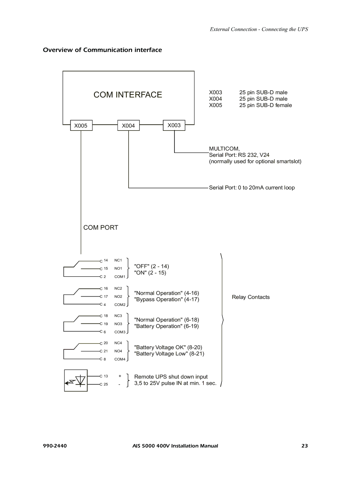
COM INTERFACE
X003 25 pin
X004 25 pin
X005 25 pin
X005X004X003
MULTICOM,
Serial Port: RS 232, V24
(normally used for optional smartslot)
Serial Port: 0 to 20mA current loop
COM PORT
| C 14 | NC1 |
| C 15 | NO1 |
| ||
| C 2 | COM1 |
| C 16 | NC2 |
| C 17 | NO2 |
| ||
| C 4 | COM2 |
| C 18 | NC3 |
| C 19 | NO3 |
| ||
| C 6 | COM3 |
| C 20 | NC4 |
| C 21 | NO4 |
| ||
C 8 | COM4 | |
"OFF" (2 - 14) "ON" (2 - 15)
"Normal Operation" | Relay Contacts | |
"Bypass Operation" | ||
|
"Normal Operation"
"Battery Operation"
"Battery Voltage OK"
"Battery Voltage Low"
| C 13 | + | Remote UPS shut down input |
| |||
| C 25 | - | 3,5 to 25V pulse IN at min. 1 sec. |
|
AIS 5000 400V Installation Manual | 23 |