Control |
| Function |
| ||
|
|
|
|
|
|
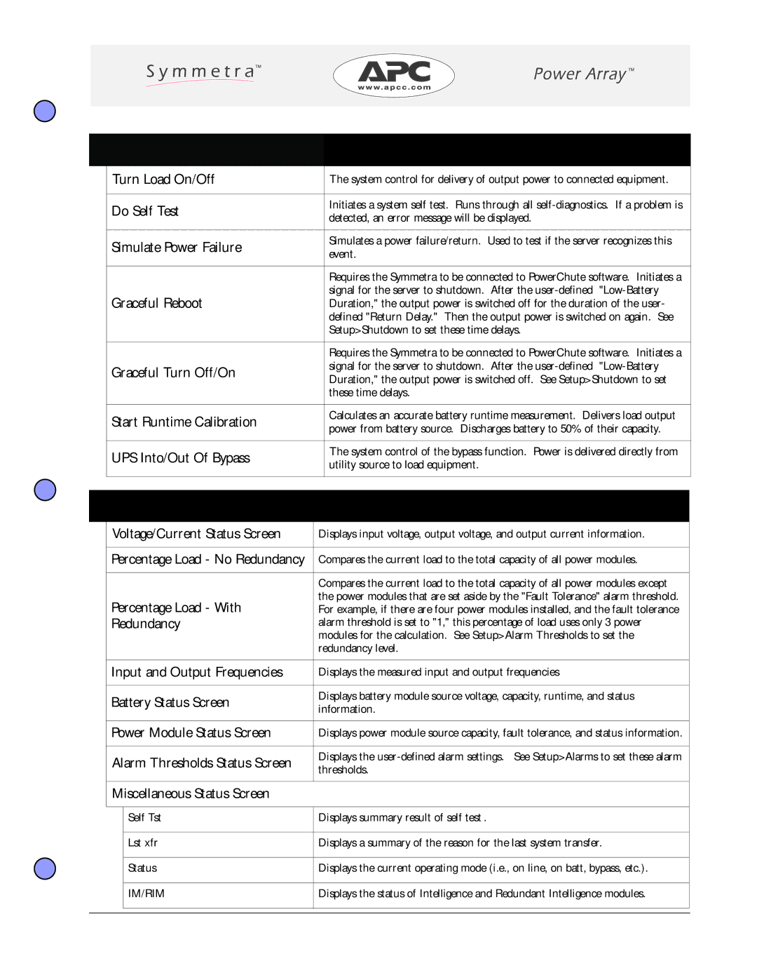
| Turn Load On/Off |
| The system control for delivery of output power to connected equipment. |
| |
|
|
|
|
|
|
| Do Self Test |
| Initiates a system self test. Runs through all |
| |
|
| detected, an error message will be displayed. |
| ||
|
|
|
|
| |
|
|
|
|
|
|
| Simulate Power Failure |
| Simulates a power failure/return. Used to test if the server recognizes this |
| |
|
| event. |
| ||
|
|
|
|
| |
|
|
|
|
|
|
|
|
|
| Requires the Symmetra to be connected to PowerChute software. Initiates a |
|
|
|
|
| signal for the server to shutdown. After the |
|
| Graceful Reboot |
| Duration," the output power is switched off for the duration of the user- |
| |
|
|
|
| defined "Return Delay." Then the output power is switched on again. See |
|
|
|
|
| Setup>Shutdown to set these time delays. |
|
|
|
|
|
|
|
|
|
|
| Requires the Symmetra to be connected to PowerChute software. Initiates a |
|
| Graceful Turn Off/On |
| signal for the server to shutdown. After the |
| |
|
| Duration," the output power is switched off. See Setup>Shutdown to set |
| ||
|
|
|
|
| |
|
|
|
| these time delays. |
|
|
|
|
|
|
|
| Start Runtime Calibration |
| Calculates an accurate battery runtime measurement. Delivers load output |
| |
|
| power from battery source. Discharges battery to 50% of their capacity. |
| ||
|
|
|
|
| |
|
|
|
|
|
|
| UPS Into/Out Of Bypass |
| The system control of the bypass function. Power is delivered directly from |
| |
|
| utility source to load equipment. |
| ||
|
|
|
|
| |
|
|
|
|
|
|
|
|
|
|
| |
Status | Function |
| |||
|
|
|
|
| |
| Voltage/Current Status Screen | Displays input voltage, output voltage, and output current information. |
| ||
|
|
|
|
| |
| Percentage Load - No Redundancy | Compares the current load to the total capacity of all power modules. |
| ||
|
|
|
|
| |
|
|
| Compares the current load to the total capacity of all power modules except |
| |
| Percentage Load - With | the power modules that are set aside by the "Fault Tolerance" alarm threshold. |
| ||
| For example, if there are four power modules installed, and the fault tolerance |
| |||
| Redundancy | alarm threshold is set to "1," this percentage of load uses only 3 power |
| ||
|
|
| modules for the calculation. See Setup>Alarm Thresholds to set the |
| |
|
|
| redundancy level. |
| |
|
|
|
|
| |
| Input and Output Frequencies | Displays the measured input and output frequencies |
| ||
|
|
|
|
| |
| Battery Status Screen | Displays battery module source voltage, capacity, runtime, and status |
| ||
| information. |
| |||
|
|
|
| ||
|
|
|
|
| |
| Power Module Status Screen | Displays power module source capacity, fault tolerance, and status information. |
| ||
|
|
|
|
| |
| Alarm Thresholds Status Screen | Displays the |
| ||
| thresholds. |
| |||
|
|
|
| ||
|
|
|
|
|
|
| Miscellaneous Status Screen |
|
|
| |
|
|
|
|
| |
|
| Self Tst | Displays summary result of self test. |
| |
|
|
|
|
| |
|
| Lst xfr | Displays a summary of the reason for the last system transfer. |
| |
|
|
|
|
| |
|
| Status | Displays the current operating mode (i.e., on line, on batt, bypass, etc.). |
| |
|
|
|
|
| |
|
| IM/RIM | Displays the status of Intelligence and Redundant Intelligence modules. |
| |
|
|
|
|
|
|
|
|
|
|
|
|
Appendix A - The PowerView Interface - Page 5 | |
|
