ADSP-2181/ADSP-2183
These
The following pins are also used by the
BR
BG
RESET
GND
The
The
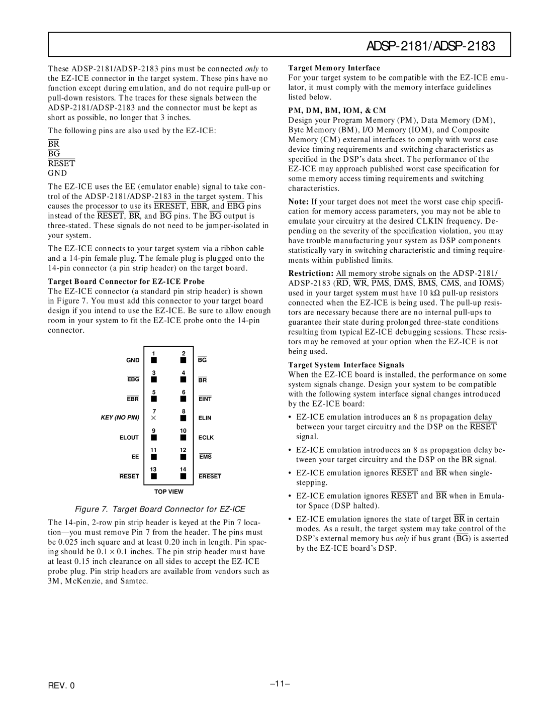
Target Board Connector for
The
Target Memory Interface
For your target system to be compatible with the
PM, DM, BM, IOM, & CM
Design your Program Memory (PM), Data Memory (DM), Byte Memory (BM), I/O Memory (IOM), and Composite Memory (CM) external interfaces to comply with worst case device timing requirements and switching characteristics as specified in the DSP’s data sheet. The performance of the
Note: If your target does not meet the worst case chip specifi- cation for memory access parameters, you may not be able to emulate your circuitry at the desired CLKIN frequency. De- pending on the severity of the specification violation, you may have trouble manufacturing your system as DSP components statistically vary in switching characteristic and timing require- ments within published limits.
Restriction: All memory strobe signals on the
GND
EBG
EBR
KEY (NO PIN)
ELOUT
EE
RESET
12
34
56
78
×![]()
9 10
1112
1314
TOP VIEW
BG
BR
EINT
ELIN
ECLK
EMS
ERESET
Target System Interface Signals
When the
• | |||||||||
| between your target circuitry and the DSP on the | RESET |
| ||||||
| signal. | ||||||||
• | |||||||||
| tween your target circuitry and the DSP on the | BR | signal. | ||||||
• |
| and |
| when single- | |||||
RESET | BR | ||||||||
| stepping. | ||||||||
• |
| and |
| when in Emula- | |||||
RESET | BR | ||||||||
| tor Space (DSP halted). | ||||||||
Figure 7. Target Board Connector for EZ-ICE
The
• |
modes. As a result, the target system may take control of the |
DSP’s external memory bus only if bus grant (BG) is asserted |
by the |
REV. 0 |