Memory Architecture
The ADSP-2181/ADSP-2183 provides a variety of memory and peripheral interface options. The key functional groups are Pro- gram Memory, Data Memory, Byte Memory, and I/O.
Program Memory is a 24-bit-wide space for storing both in- struction opcodes and data. The ADSP-2181/ADSP-2183 has 16K words of Program Memory RAM on chip, and the capabil- ity of accessing up to two 8K external memory overlay spaces using the external data bus. Both an instruction opcode and a data value can be read from on-chip program memory in a single cycle.
Data Memory is a 16-bit-wide space used for the storage of data variables and for memory-mapped control registers. The ADSP-2181/ADSP-2183 has 16K words on Data Memory RAM on chip, consisting of 16,352 user-accessible locations and 32 memory-mapped registers. Support also exists for up to two 8K external memory overlay spaces through the external data bus.
Byte Memory provides access to an 8-bit wide memory space through the Byte DMA (BDMA) port. The Byte Memory inter- face provides access to 4 MBytes of memory by utilizing eight data lines as additional address lines. This gives the BDMA Port an effective 22-bit address range. On power-up, the DSP can automatically load bootstrap code from byte memory.
I/O Space allows access to 2048 locations of 16-bit-wide data. It is intended to be used to communicate with parallel periph- eral devices such as data converters and external registers or latches.
Program Memory
The ADSP-2181/ADSP-2183 contains a 16K × 24 on-chip program RAM. The on-chip program memory is designed to al- low up to two accesses each cycle so that all operations can complete in a single cycle. In addition, the ADSP-2181/ADSP- 2183 allows the use of 8K external memory overlays.
The program memory space organization is controlled by the MMAP pin and the PMOVLAY register. Normally, the ADSP- 2181/ADSP-2183 is configured with MMAP = 0 and program memory organized as shown in Figure 4.
0x3FFF
8K INTERNAL
(PMOVLAY = 0, MMAP = 0)
OR
EXTERNAL 8K
(PMOVLAY = 1 or 2,
MMAP = 0)
0x2000
0x1FFF
8K INTERNAL
0x0000
Figure 4. Program Memory (MMAP = 0)
There are 16K words of memory accessible internally when the PMOVLAY register is set to 0. When PMOVLAY is set to something other than 0, external accesses occur at addresses 0x2000 through 0x3FFF. The external address is generated as shown in Table II.
Table II.
PMOVLAY | Memory | A13 | A12:0 |
| | | |
0 | Internal | Not Applicable | Not Applicable |
| | | |
1 | External | 0 | 13 LSBs of Address |
| Overlay 1 | | Between 0x2000 |
| | | and 0x3FFF |
| | | |
2 | External | 1 | 13 LSBs of Address |
| Overlay 2 | | Between 0x2000 |
| | | and 0x3FFF |
| | | |
This organization provides for two external 8K overlay segments using only the normal 14 address bits. This allows for simple program overlays using one of the two external segments in place of the on-chip memory. Care must be taken in using this overlay space in that the processor core (i.e., the sequencer) does not take into account the PMOVLAY register value. For example, if a loop operation was occurring on one of the exter- nal overlays and the program changes to another external over- lay or internal memory, an incorrect loop operation could occur. In addition, care must be taken in interrupt service routines as the overlay registers are not automatically saved and restored on the processor mode stack.
For ADSP-2100 Family compatibility, MMAP = 1 is allowed. In this mode, booting is disabled and overlay memory is dis- abled (PMOVLAY must be 0). Figure 5 shows the memory map in this configuration.
0x3FFF
INTERNAL 8K
(PMOVLAY = 0, MMAP = 1)
0x2000
0x1FFF
8K EXTERNAL
0x0000
Figure 5. Program Memory (MMAP = 1)
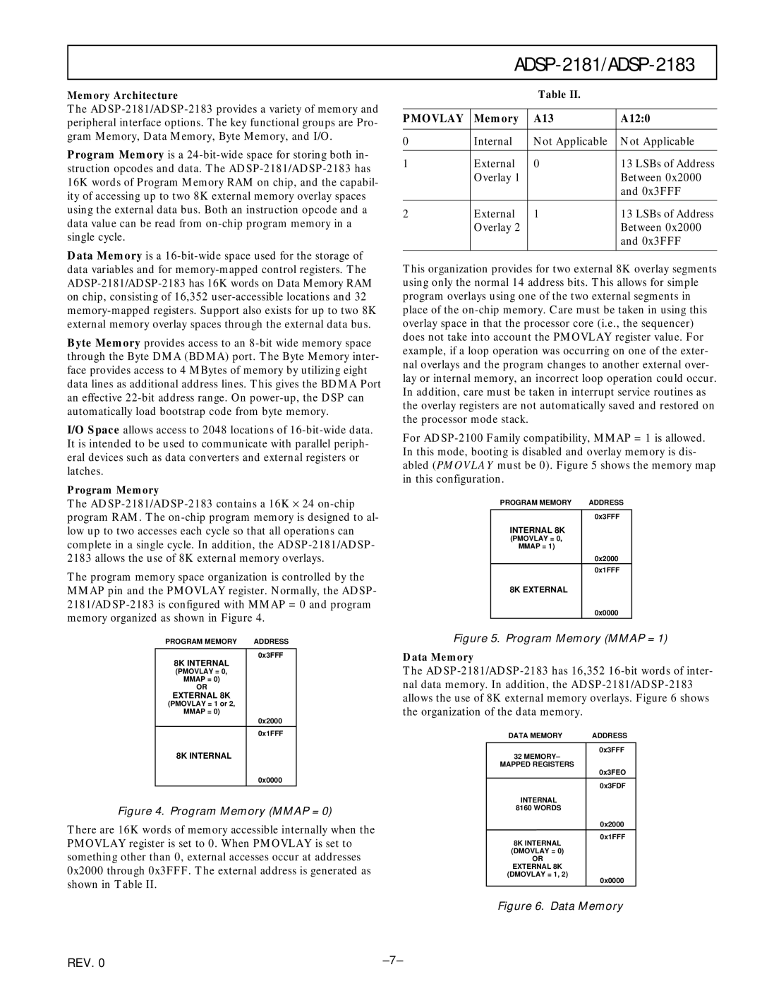
Data Memory
The ADSP-2181/ADSP-2183 has 16,352 16-bit words of inter- nal data memory. In addition, the ADSP-2181/ADSP-2183 allows the use of 8K external memory overlays. Figure 6 shows the organization of the data memory.
0x3FFF
32MEMORY– MAPPED REGISTERS
0x3FEO
0x3FDF
INTERNAL 8160 WORDS
0x2000
0x1FFF
8K INTERNAL
(DMOVLAY = 0)
OR
EXTERNAL 8K
(DMOVLAY = 1, 2)
0x0000
Figure 6. Data Memory