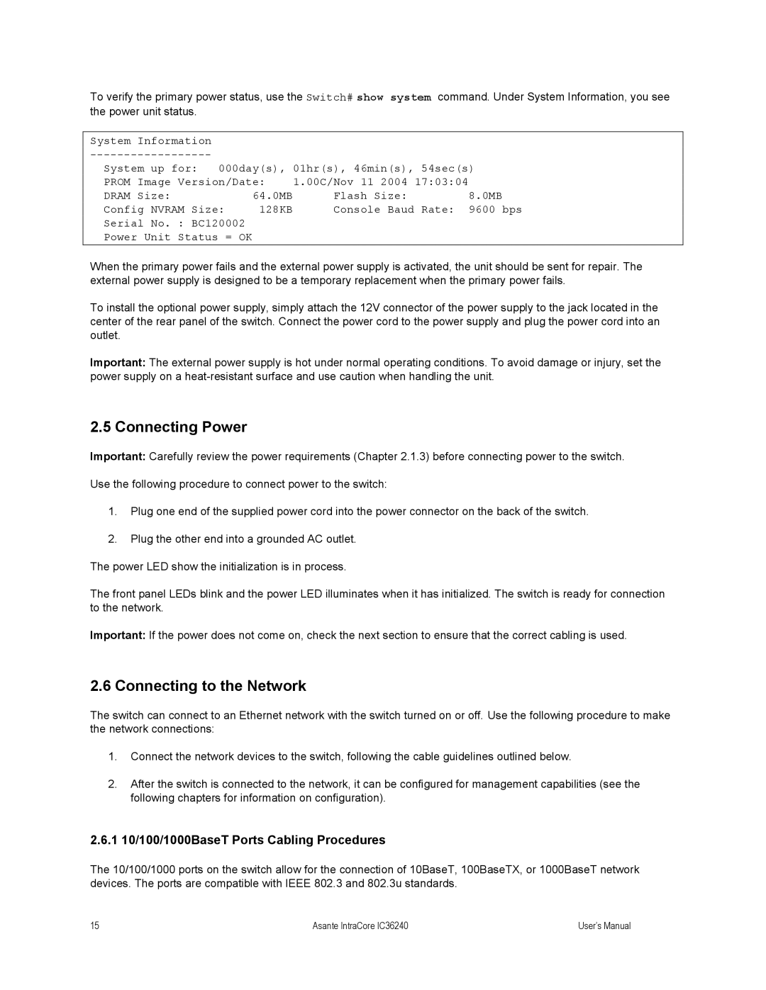
To verify the primary power status, use the Switch# show system command. Under System Information, you see the power unit status.
System Information |
|
|
|
| 01hr(s), 46min(s), 54sec(s) | ||
System up for: 000day(s), | |||
PROM Image Version/Date: | 1.00C/Nov 11 2004 17:03:04 | 8.0MB | |
DRAM Size: | 64.0MB | Flash Size: | |
Config NVRAM Size: | 128KB | Console Baud Rate: | 9600 bps |
Serial No. : BC120002 |
|
|
|
Power Unit Status = OK |
|
|
|
When the primary power fails and the external power supply is activated, the unit should be sent for repair. The external power supply is designed to be a temporary replacement when the primary power fails.
To install the optional power supply, simply attach the 12V connector of the power supply to the jack located in the center of the rear panel of the switch. Connect the power cord to the power supply and plug the power cord into an outlet.
Important: The external power supply is hot under normal operating conditions. To avoid damage or injury, set the power supply on a
2.5 Connecting Power
Important: Carefully review the power requirements (Chapter 2.1.3) before connecting power to the switch. Use the following procedure to connect power to the switch:
1.Plug one end of the supplied power cord into the power connector on the back of the switch.
2.Plug the other end into a grounded AC outlet.
The power LED show the initialization is in process.
The front panel LEDs blink and the power LED illuminates when it has initialized. The switch is ready for connection to the network.
Important: If the power does not come on, check the next section to ensure that the correct cabling is used.
2.6 Connecting to the Network
The switch can connect to an Ethernet network with the switch turned on or off. Use the following procedure to make the network connections:
1.Connect the network devices to the switch, following the cable guidelines outlined below.
2.After the switch is connected to the network, it can be configured for management capabilities (see the following chapters for information on configuration).
2.6.1 10/100/1000BaseT Ports Cabling Procedures
The 10/100/1000 ports on the switch allow for the connection of 10BaseT, 100BaseTX, or 1000BaseT network devices. The ports are compatible with IEEE 802.3 and 802.3u standards.
15 | Asante IntraCore IC36240 | User’s Manual |