Chapter 1: Introduction
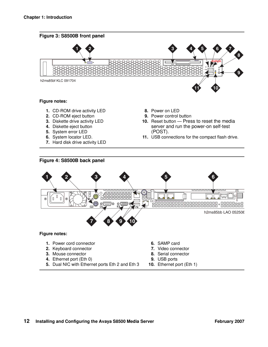
Figure 3: S8500B front panel
1 | 2 | 3 | 4 | 5 | 6 | 7 |
8
9
| h2ms85bf KLC 091704 |
|
|
|
|
| |
|
|
|
| 11 | 10 |
| |
Figure notes: |
|
|
|
|
| ||
1. | 8. | Power on LED |
|
|
| ||
2. | 9. | Power control button |
|
|
| ||
3. | Diskette drive activity LED | 10. | Reset button — Press to reset the media | ||||
4. | Diskette eject button |
| server and run the | ||||
5. | System error LED |
| (POST). |
|
|
| |
6. | System locator LED. | 11. | USB connections for the compact flash drive. | ||||
7.Hard disk drive activity LED
Figure 4: S8500B back panel
1 | 2 | 3 | 4 | 5 | 6 |
![]()
![]()
![]() 2
2
|
|
|
|
|
| h2ms85bb LAO 052506 |
| 7 | 8 | 9 | 10 |
|
|
Figure notes: |
|
|
|
|
| |
1. | Power cord connector |
|
|
| 6. | SAMP card |
2. | Keyboard connector |
|
|
| 7. | Video connector |
3. | Mouse connector |
|
|
| 8. | Serial connector |
4. | Ethernet port (Eth 0) |
|
|
| 9. | USB ports |
5. | Dual NIC with Ethernet ports Eth 2 and Eth 3 | 10. | Ethernet port (Eth 1) | |||
|
|
|
|
|
|
|
12 Installing and Configuring the Avaya S8500 Media Server | February 2007 |