CONNECTING THE VSSI-PRO
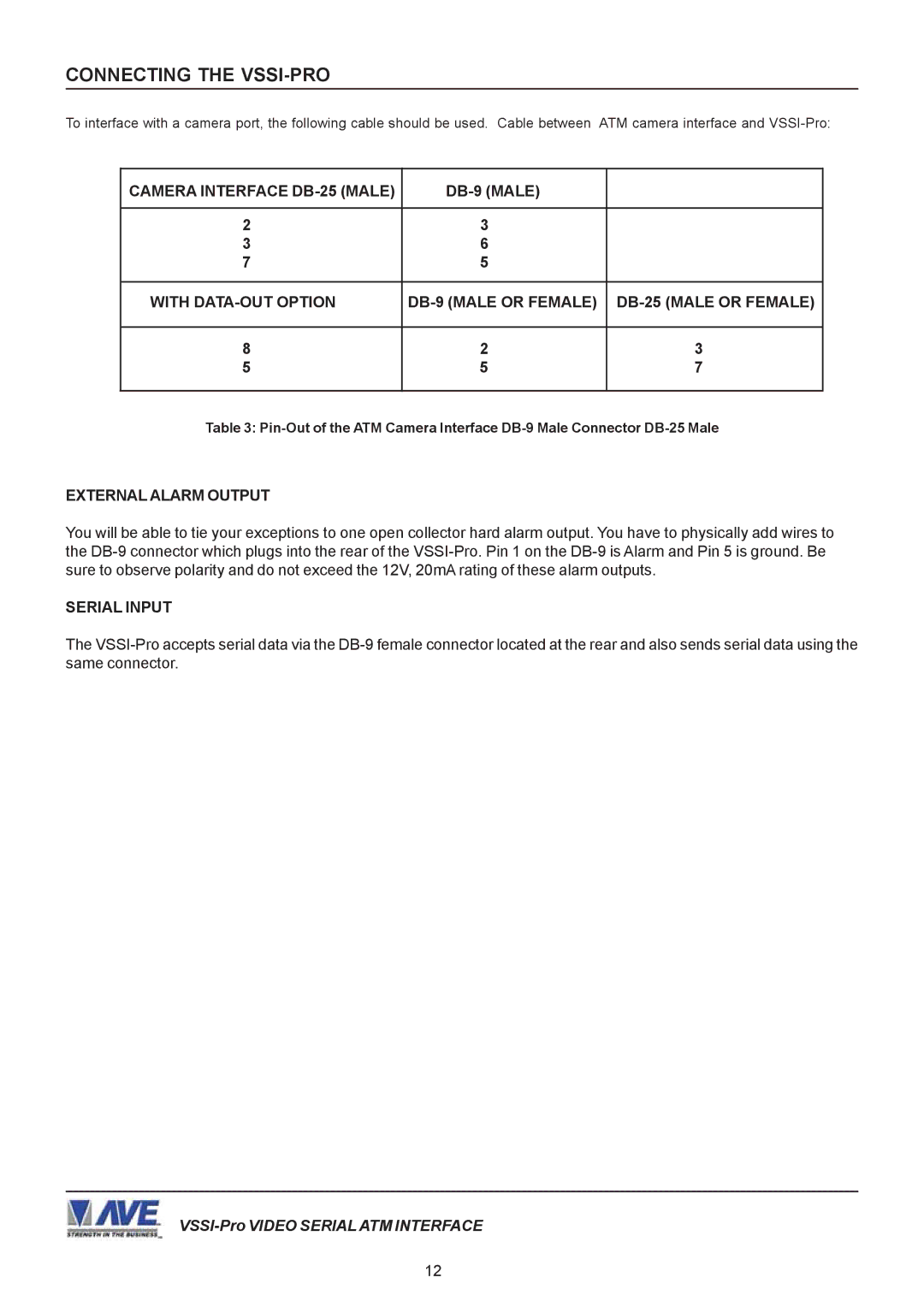
To interface with a camera port, the following cable should be used. Cable between ATM camera interface and VSSI-Pro:
CAMERA INTERFACE DB-25 (MALE) | DB-9 (MALE) | |
| | |
2 | 3 | |
3 | 6 | |
7 | 5 | |
| | |
WITH DATA-OUT OPTION | DB-9 (MALE OR FEMALE) | DB-25 (MALE OR FEMALE) |
| | |
8 | 2 | 3 |
5 | 5 | 7 |
| | |
Table 3: Pin-Out of the ATM Camera Interface DB-9 Male Connector DB-25 Male
EXTERNAL ALARM OUTPUT
You will be able to tie your exceptions to one open collector hard alarm output. You have to physically add wires to the DB-9 connector which plugs into the rear of the VSSI-Pro. Pin 1 on the DB-9 is Alarm and Pin 5 is ground. Be sure to observe polarity and do not exceed the 12V, 20mA rating of these alarm outputs.
SERIAL INPUT
The VSSI-Pro accepts serial data via the DB-9 female connector located at the rear and also sends serial data using the same connector.
VSSI-Pro VIDEO SERIAL ATM INTERFACE