VSSI-PRO
VSSI-PRO
Contents
Tables
Appendices
Figures
Can be set to MM/DD/YY, DD/MM/YY or YY/MM/DD
Features
Specifications
Specifications
Watchdog Timer Hardware and Software
Connecting the VSSI-PRO
Connecting the VSSI-PRO Introduction
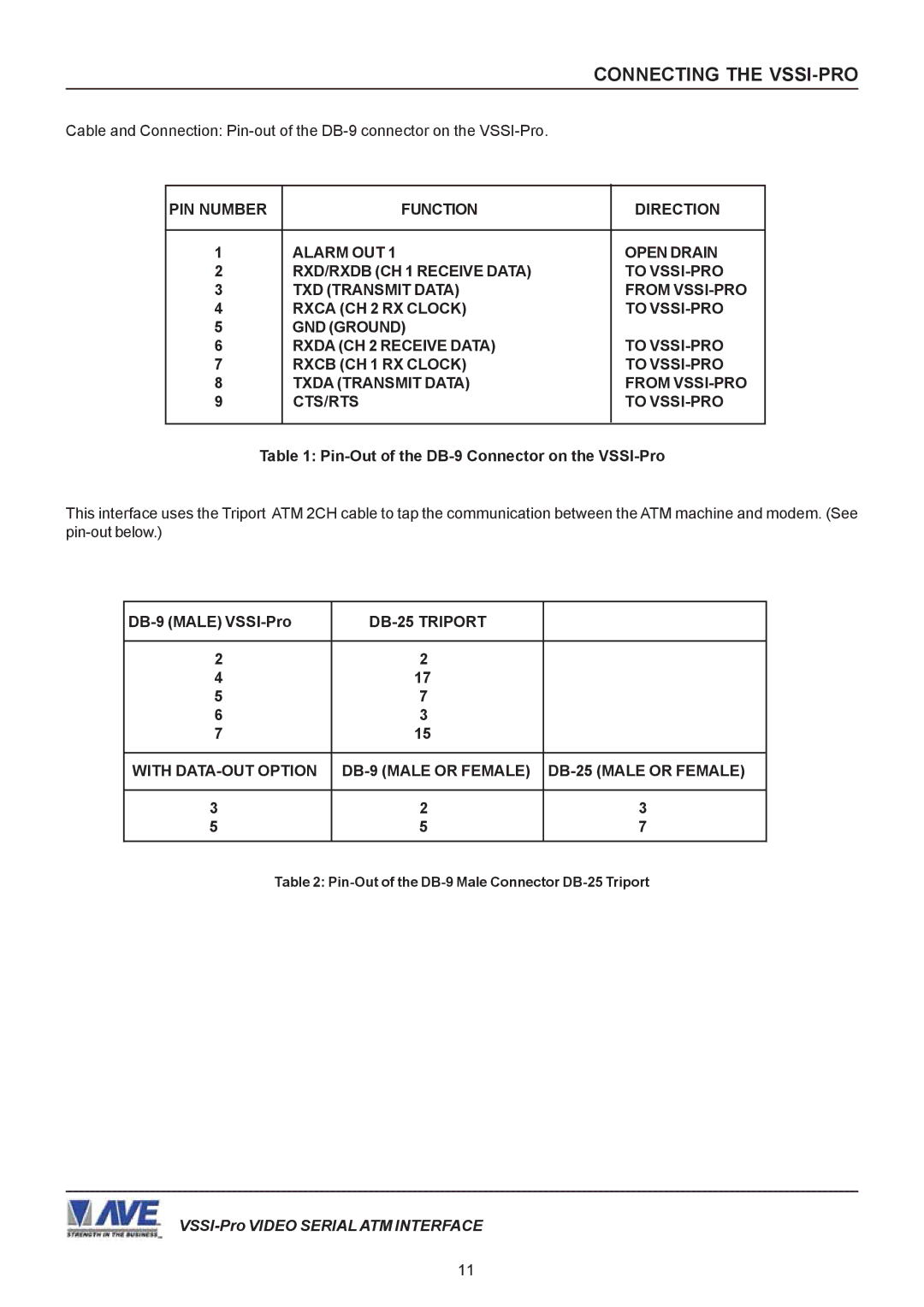
VSSI-PRO Connections
ATM to VSSI-PRO Installation
VSSI-PRO Video Connection
DB-9 Male VSSI-Pro
Serial Input
External Alarm Output
Camera Interface DB-25 Male
User Front Panel Controls
Programming the VSSI-PRO
FEW Words about Programming
Programming Getting Started
Setup
Main-Menu for Programming the VSSI-Pro
Programming Menus
Fujitsu
Sdlc Format CAT ELF Exit
Bisync Format Exit
Async Format Exit
VSSI-PRO
Tcpip 232 Adapter Connections
Tcpip Format Tcpip Debugging Exit
Tcpip 232 Debugging Mode
Text Grayscale
Screen Setup
Custom Exit
Clock Sub-Menu
Titler
More on TIME/DATE Locking
Hhmm, hhmmss hhmmAM, hhmmssAM hhmmPM, hhmmssPM
Titler SET Titler Exit
Choices NONE, 6, 12, 20, 30, 60, 120, 180, 300 in seconds
Text Display
Screen Blank
Choices 1 through
Communication
Choices 7 or
Parity
Choices NONE, ODD, Even
Parity None Data Bits Exit
Address Setup ANY Baud Rate
Address Setup
Async Bisync Sdlc Exit
Choices Ascii or Ebcdic
Address SET UP ANY Data Encode NRZ Data Coding Ascii Exit
Choices NRZ, NRZI, Nrzid
ON-SCREEN Flags
Hard Alarm Output
Exception Report
View Exceptions
Exception History SET Exception Output Time Stamp Exit
Exception History
Total Exceptions
Dest ID SCR ID Exit
Example
VSSI-Pro with DVR Connections
With Drawal
Time Search Time Search Setting
Exception no
Exception no Display Output Exception String No Sale Range
Operator None Exit
Application Note �
Choices
Welcome to Bank of America
Operator
Defining the Operator
Exiting the Range Field
Alarm Outputs
Navigating the Range and the Exception String
Defining the Range
RTS
Alarm no
Alarm Trigger
None Sends no alarming data
Choices 000, 002, 004,..., 236, 238
Choices NO, NC
Choices NONE, FLASH, REVERSE, Flash
Display Text
Triggered Text
Display Text OFF Output Text SET Triggered Text Exit
Receive RX Test
Programming the VSSI-PRO TEST/DEMO Mode
Port 1 Test
RX Baudrate TX Baudrate Parity Data BIT Handshaking Echoing
Data HEX MS nibble HEX LS nibble
Protocol RX Baudrate TX Baudrate Data Encode Receiving
Receive RX Test Transmit TX Test RX/TX Test Exit
Protocol RX Baudrate TX Baudrate Data Encode Dumping Data
Protocol RX Baudrate TX Baudrate Data Encode
Capture to Port
CHB RX Byte
Protocol Async
Data Encode NRZ Ascii Capture Data to
CHA RX Byte
Withdrawal From Checking
Transaction Begin
TST ATM Raleigh Highwoods Blvd Raleigh #
CODE*SERIAL Amount
DOWNLOAD/UPLOAD Setup Using VSSI-Pro to VSSI-Pro
DOWNLOAD/UPLOAD Setup Using VSSI-PRO to VSSI-PRO
DOWNLOAD/UPLOAD Setup Sub-Menu
Download Setup Upload Setup Exit
UP and Down
DOWNLOAD/UPLOAD Setup Using a PC
UP/DOWN
SET
Performing a Data Dump
Data Dump Connections Appendix a
Data Dump Connections
Sdlc / Bisync Camera Port / Journal / Tcpip
Appendix B
Problem Solving Guide
Master Reset the VSSI-PRO
Master Reset the VSSI-Pro
Appendix D
Frequently Asked Questions Regarding ATM Interfacing
Appendix E
RS-485NETWORKER
PC Software with ATM Data
Appendix F
TTL
Hard Alarm Output Appendix G
DB-25 Female DB-9 Male
Appendix H
PIN Assignment for Time Search Function Appendix
Appendix J
Limited Warranty
Limited Warranty
Appendix K
Appendix K
Appendix K
Appendix K