DATA DUMP CONNECTIONS | APPENDIX A |
DATA DUMP CONNECTIONS
To execute a data dump you will have to connect wires from the
SDLC / BISYNC | CAMERA PORT / JOURNAL / TCPIP | Com 1 | Com 2 |
|
|
|
|
3 | 8 | 2 | 3 |
5 | 5 | 5 | 7 |
|
|
|
|
| Table 1A: Data Dump Connections |
| |
Triport MODEM
ATM |
| ||||
| tor |
| |||
|
|
|
|
| |
|
|
|
|
|
|
| |||||
CAMERA | tor | COM 1 | |||
|
| ||||
|
| COM 2 | |||
|
|
| |||
MONITOR
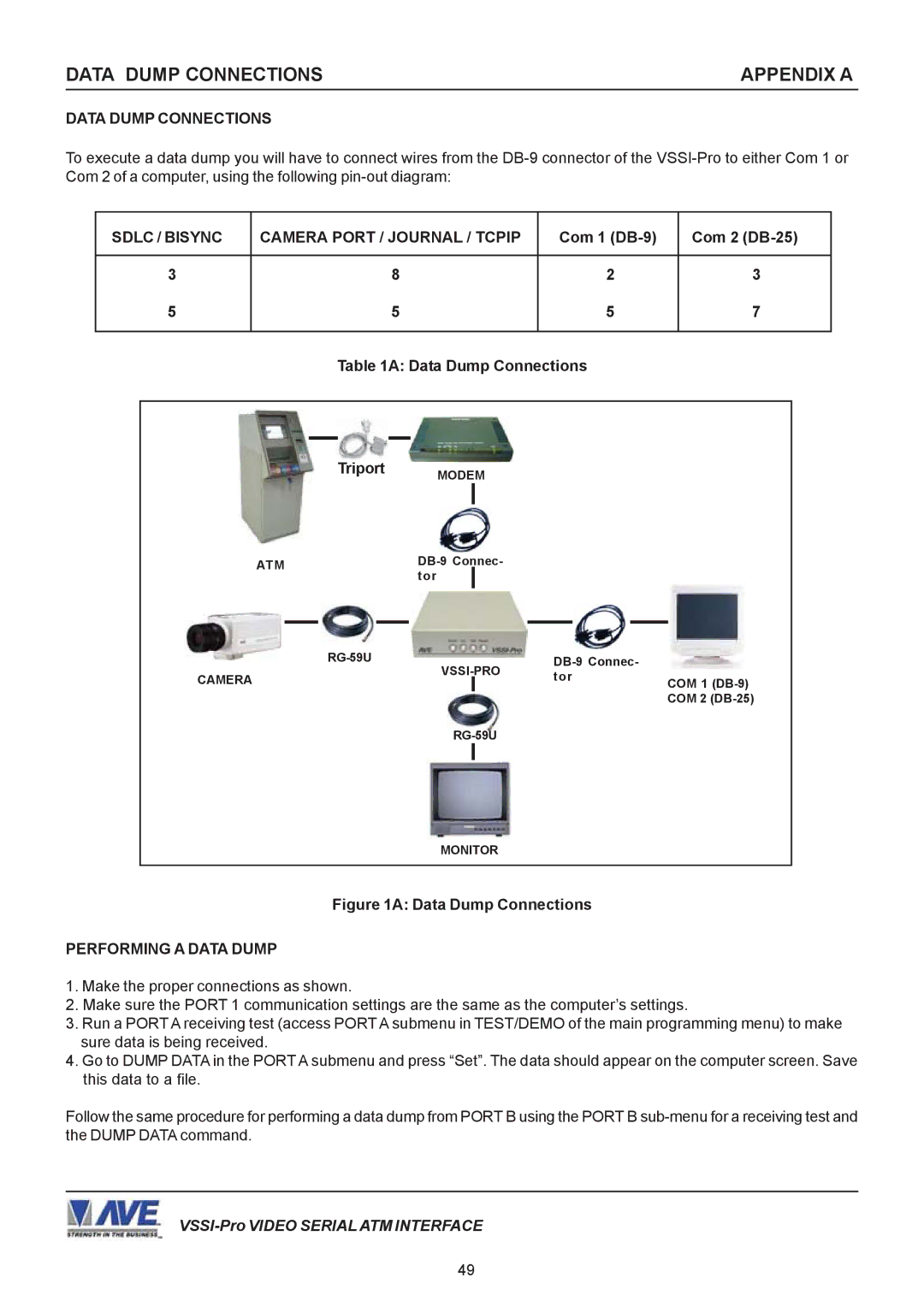
Figure 1A: Data Dump Connections
PERFORMING A DATA DUMP
1.Make the proper connections as shown.
2.Make sure the PORT 1 communication settings are the same as the computer’s settings.
3.Run a PORT A receiving test (access PORT A submenu in TEST/DEMO of the main programming menu) to make sure data is being received.
4.Go to DUMP DATA in the PORT A submenu and press “Set”. The data should appear on the computer screen. Save this data to a file.
Follow the same procedure for performing a data dump from PORT B using the PORT B
49