AVE ATM to VSSI-PRO Installation, VSSI-PRO Video Connection, VSSI-PRO Connections

Models: VSSI-PRO

1 64
Download 64 pages 57.17 Kb
Page 10
Image 10

CONNECTING THE VSSI-PRO

ATM TO VSSI-PRO INSTALLATION

Locate the connector on the ATM’s modem and loosen the 2 retaining screws, then quickly plug in the appropriate DB- 25 connector of the triport into the modem. Next plug the modem cable into the other DB-25 connector of the triport, and plug the DB-9 connector into the VSSI-Pro.

NOTE "

Make sure no one is operating the ATM when you disconnect the DB-25 connector.

IMPORTANT

The input video level must be 1V P-P. If this level is not maintained within +/- 20%, the VSSI-Pro will have difficulty locking the character display over the input video source. If the display is jumpy or tears this is a common symptom of input video level that is too high or too low.

VSSI-PRO VIDEO CONNECTION

The video input to the VSSI-Pro is a standard BNC connector terminated at 75 ohm.

After completing the interface installation, connect the video input source to the video input BNC on the rear of the VSSI-Pro. The BNC video output connects to the video system (DVR, VCR, Quad, switcher, Multiplexer, or monitor).

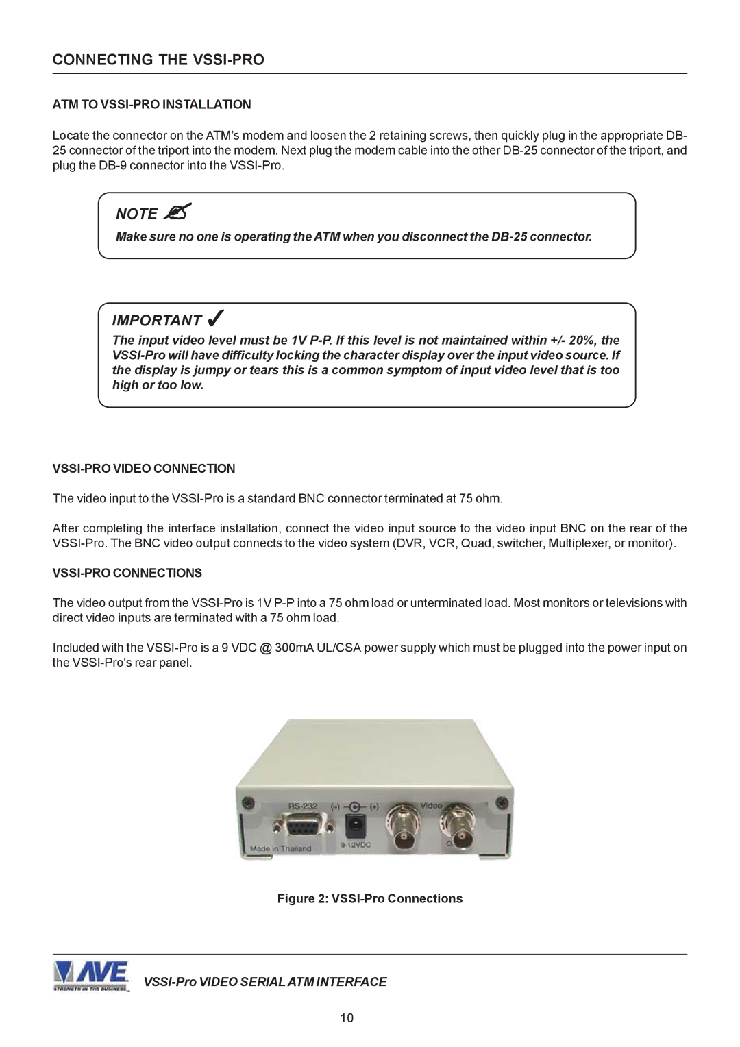
VSSI-PRO CONNECTIONS

The video output from the VSSI-Pro is 1V P-P into a 75 ohm load or unterminated load. Most monitors or televisions with direct video inputs are terminated with a 75 ohm load.

Included with the VSSI-Pro is a 9 VDC @ 300mA UL/CSA power supply which must be plugged into the power input on the VSSI-Pro's rear panel.

Figure 2: VSSI-Pro Connections

VSSI-Pro VIDEO SERIAL ATM INTERFACE

10

Page 10
Image 10
AVE operation manual ATM to VSSI-PRO Installation, VSSI-PRO Video Connection, VSSI-PRO Connections