Netra 1290 Server Installation Guide
Please Recycle
Contents
Setting Up 39 Setup Process
Netra 1290 Server Connections
Figures
System Controller and I/O Assembly Locations
Tables
Viii Netra 1290 Server Installation Guide May
Using Unix Commands
How This Document Is Organized
Shell Prompts
Typographic Conventions
Third-Party Web Sites
Related Documentation
Documentation, Support, and Training
Sun Welcomes Your Comments
Unpacking the Server
To Unpack the Server
Remove and unpack the shipping kit
1Opening the Shipping Carton
Remove the outer carton
2Removing the Carton Pieces
Installing Slide Rails
Remove the internal saddle
Adjusting the Slide Rail Assembly
N F I R E
To Install the Inner Rails on the Server
Spring clip should engage
To Prepare the Rails for 2-Post Installations
Repeat through for the second inner rail
To Install the Slide Rail Assemblies in the Bottom Position
To Install the Slide Rail Assemblies in the Top Position
To Install the Slide Rail Assemblies in the Bottom Position
Front bracket Rear bracket Secured to outer cabinet holes
To Install the Slide Rail Assemblies in the Top Position
Netra 1290 Server Installation Guide May
Secure the front bracket with two No -32 UNF screws
Installing the Server in a Cabinet
To Prepare to Install the Server in the Cabinet
Repeat Step a and Step b for the second front bezel door
Remove the shipping cradle bolts Figure
To Mount the Server in the Cabinet
9Removing the Shipping Cradle Bolts
Latches on each side must click out, locking the rails
Outer rails Inner rails
12Removing the Shipping Cradle
Retract the cabinet stabilization mechanism as required
13Pushing the Server Into the System Cabinet
Reattach the front doors of the server
Installing Slide Rail Lock Nuts
To Install the Lock Nuts
Slide the server into the system cabinet
15Inserting and Tightening the Spacers
Installing the Cable Management Arm
To Install the CMA-Lite on To Install the CMA-800 on
To Install the CMA-Lite
18CMA-Lite Cable Management Arm
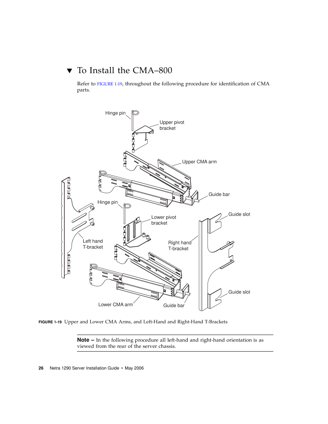
To Install the CMA-800
20Upper and Lower Pivot Bracket Mounting Holes
Hinge pin Upper pivot bracket Upper CMA arm
Hinge pin Lower pivot bracket Lower CMA arm
Slide rail Left hand T-bracket
Slide rail Right hand T-bracket
25Attaching the Upper and Lower CMA Arms to the T-Bracket
Connecting Power Cables
To Connect the Power Cables
Connecting Consoles to the System Controller
To Connect the Initial Administrative Console
Set up the system console
To Connect the Administrative Console
Set up the chosen administrative console
To Connect the I/O Assemblies
Connecting the I/O Assemblies
Installing Additional Hardware
Installing Additional Peripheral Devices
Setting Up
Setup Process
To Install and Cable the Hardware
Setting Up the Hardware
On/Standby Switch
To Power On Using the On/Standby Switch
Powering On the Server
Disabling Operation of the On/Standby Switch
To disable the On/Standby switch, use the setupsc command
At the lom prompt, type
Bringing the Server to Standby Mode
To Power On Using the LOM poweron Command
Press the left side of the system On/Standby switch
To Bring the System to Standby Mode From the LOM Port
For an abrupt power off, type
At the system prompt, type
At the LOM prompt, type the SC password command
Setting Up the Server
To Set Up the Password
To Set the Date and Time
Answer the questions in the script
To Configure Network Parameters
At the LOM prompt, type setupnetwork
Access the LOM prompt
Installing and Booting the Solaris Operating System
To Install and Boot the Solaris Operating System
If necessary, install the Solaris Operating System
Installing the Lights Out Management Packages
To power on the server, type poweron
To Install the LOM Drivers
As superuser, type
’type=ddipseudoname=lomp
To Install the LOM Utility
To Install the LOM Manual Pages
# pkgadd -d . SUNWlomm
Netra 1290 Server Installation Guide May
Netra 1290 Server Connections
External I/O Connection Locations
PCI+ Ibssc Assemblies
Figure A-1External I/O Connection Locations
Scsi Connector
SCSI3
Alarms Port
Scsi Implementation
Table A-3Alarms Service Port Connector Pinout
NET0/NET1 Ethernet Ports
10/100BASE-T LOM Ethernet Port
NET
LOM Serial a and Serial B Ports
Twisted-Pair Ethernet Cable-Type Connectivity
LOM Serial a Serial B
Using a DB-25 Adapter for Your Serial Link
Using a DB-9 Adapter for Your Serial Link
Netra 1290 Server Installation Guide May
Index
Setupnetwork command