PACKAGED ROOFTOP
AIR CONDITIONING UNITS
INSTALLATION, OPERATION & MAINTENANCE | New Release | Form |
|
|
|
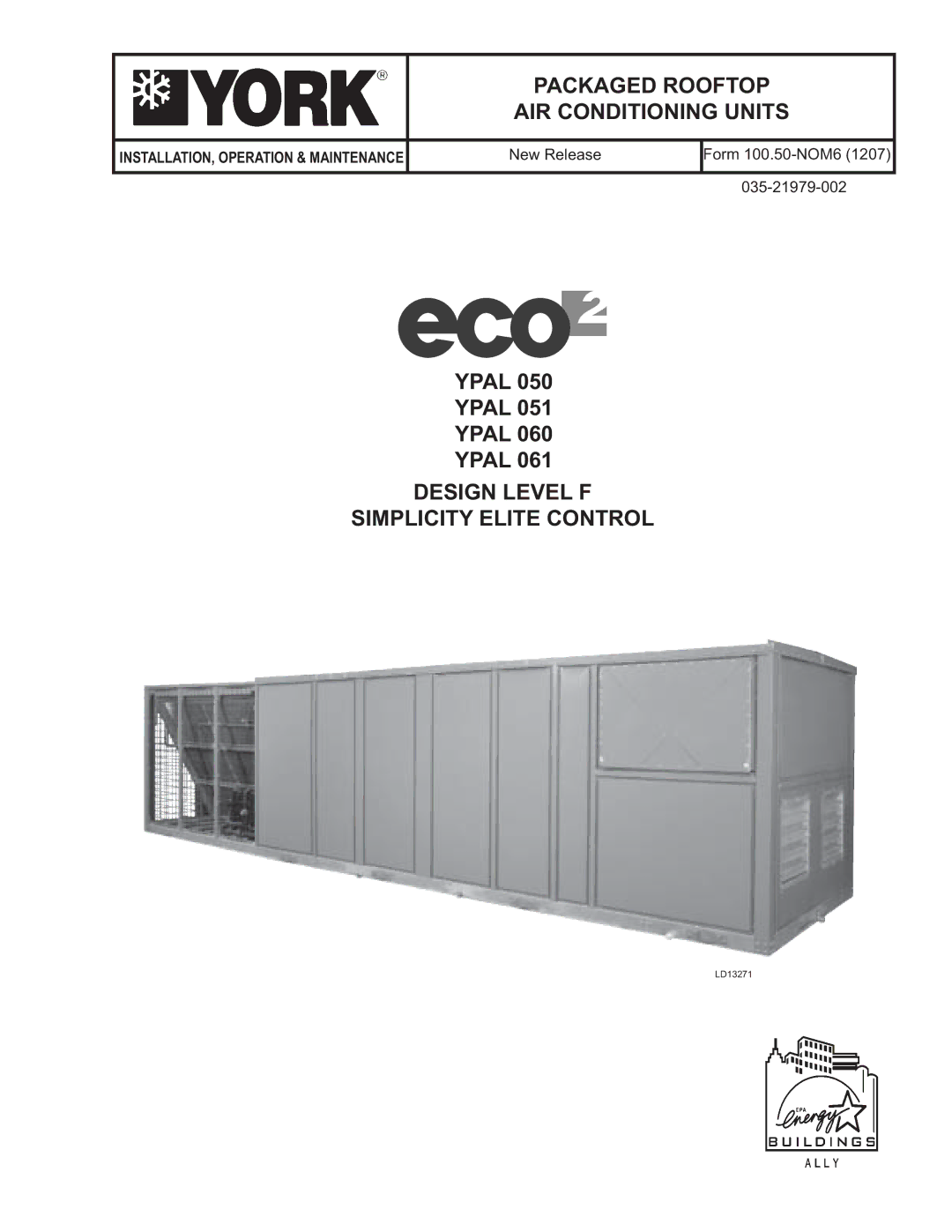
YPAL 050
YPAL 051
YPAL 060
YPAL 061
DESIGN LEVEL F
SIMPLICITY ELITE CONTROL
LD13271
INSTALLATION, OPERATION & MAINTENANCE | New Release | Form |
|
|
|
YPAL 050
YPAL 051
YPAL 060
YPAL 061
LD13271