Installation
FILTERS
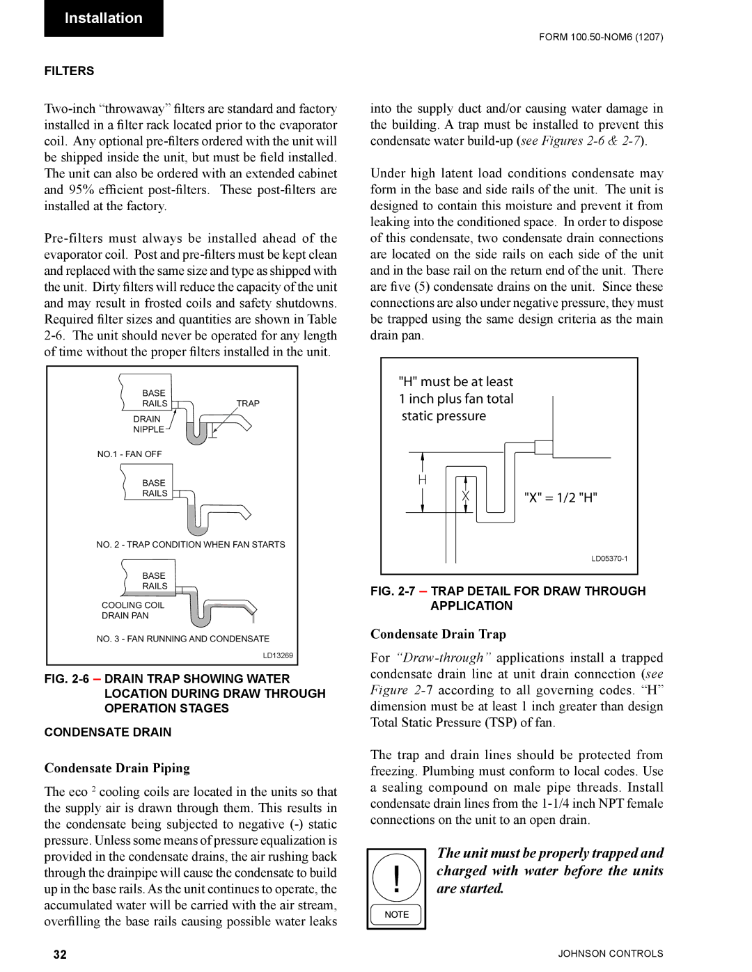
BASE
RAILS ![]() TRAP
TRAP
DRAIN
NIPPLE
NO.1 - FAN OFF
BASE
RAILS
NO. 2 - TRAP CONDITION WHEN FAN STARTS
BASE
RAILS
COOLING COIL
DRAIN PAN
NO. 3 - FAN RUNNING AND CONDENSATE
LD13269
FIG. 2-6 – DRAIN TRAP SHOWING WATER LOCATION DURING DRAW THROUGH OPERATION STAGES
CONDENSATE DRAIN
Condensate Drain Piping
The eco 2 cooling coils are located in the units so that the supply air is drawn through them. This results in the condensate being subjected to negative
FORM
into the supply duct and/or causing water damage in the building. A trap must be installed to prevent this condensate water
Under high latent load conditions condensate may form in the base and side rails of the unit. The unit is designed to contain this moisture and prevent it from leaking into the conditioned space. In order to dispose of this condensate, two condensate drain connections are located on the side rails on each side of the unit and in the base rail on the return end of the unit. There are five (5) condensate drains on the unit. Since these connections are also under negative pressure, they must be trapped using the same design criteria as the main drain pan.
"H" must be at least 1 inch plus fan total static pressure
"X" = 1/2 "H"
FIG. 2-7 – TRAP DETAIL FOR DRAW THROUGH APPLICATION
Condensate Drain Trap
For
The trap and drain lines should be protected from freezing. Plumbing must conform to local codes. Use a sealing compound on male pipe threads. Install condensate drain lines from the
The unit must be properly trapped and charged with water before the units are started.
32 | JOHNSON CONTROLS |