Service
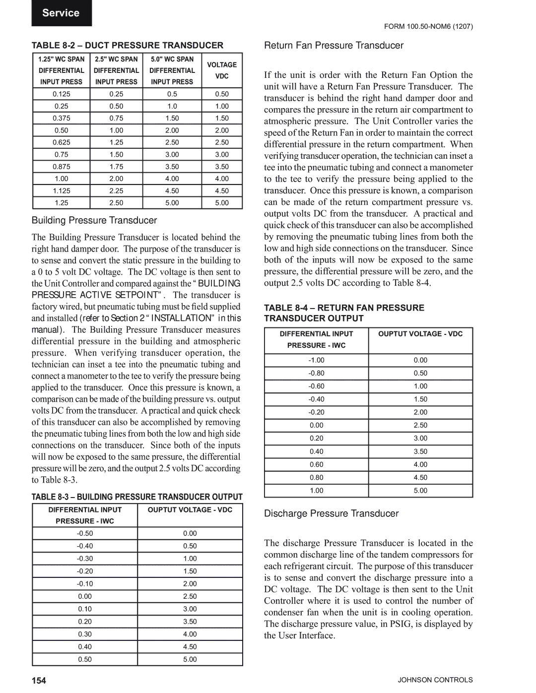
TABLE 8-2 – DUCT PRESSURE TRANSDUCER
1.25" WC SPAN | 2.5" WC SPAN | 5.0" WC SPAN | VOLTAGE | |
DIFFERENTIAL | DIFFERENTIAL | DIFFERENTIAL | ||
VDC | ||||
INPUT PRESS | INPUT PRESS | INPUT PRESS | ||
| ||||
0.125 | 0.25 | 0.5 | 0.50 | |
0.25 | 0.50 | 1.0 | 1.00 | |
0.375 | 0.75 | 1.50 | 1.50 | |
0.50 | 1.00 | 2.00 | 2.00 | |
|
|
|
| |
0.625 | 1.25 | 2.50 | 2.50 | |
0.75 | 1.50 | 3.00 | 3.00 | |
0.875 | 1.75 | 3.50 | 3.50 | |
1.00 | 2.00 | 4.00 | 4.00 | |
1.125 | 2.25 | 4.50 | 4.50 | |
1.25 | 2.50 | 5.00 | 5.00 |
Building Pressure Transducer
The Building Pressure Transducer is located behind the right hand damper door. The purpose of the transducer is to sense and convert the static pressure in the building to a 0 to 5 volt DC voltage. The DC voltage is then sent to the Unit Controller and compared against the “BUILDING PRESSURE ACTIVE SETPOINT”. The transducer is factory wired, but pneumatic tubing must be field supplied and installed (refer to Section 2 “INSTALLATION” in this manual). The Building Pressure Transducer measures differential pressure in the building and atmospheric pressure. When verifying transducer operation, the technician can inset a tee into the pneumatic tubing and connect a manometer to the tee to verify the pressure being applied to the transducer. Once this pressure is known, a comparison can be made of the building pressure vs. output volts DC from the transducer. Apractical and quick check of this transducer can also be accomplished by removing the pneumatic tubing lines from both the low and high side connections on the transducer. Since both of the inputs will now be exposed to the same pressure, the differential pressure will be zero, and the output 2.5 volts DC according to Table
TABLE
DIFFERENTIAL INPUT | OUPTUT VOLTAGE - VDC |
PRESSURE - IWC |
|
0.00 | |
|
|
0.50 | |
|
|
1.00 | |
|
|
1.50 | |
|
|
2.00 | |
|
|
0.00 | 2.50 |
|
|
0.10 | 3.00 |
|
|
0.20 | 3.50 |
|
|
0.30 | 4.00 |
|
|
0.40 | 4.50 |
|
|
0.50 | 5.00 |
|
|
FORM
Return Fan Pressure Transducer
If the unit is order with the Return Fan Option the unit will have a Return Fan Pressure Transducer. The transducer is behind the right hand damper door and compares the pressure in the return air compartment to atmospheric pressure. The Unit Controller varies the speed of the Return Fan in order to maintain the correct differential pressure in the return compartment. When verifying transducer operation, the technician can inset a tee into the pneumatic tubing and connect a manometer to the tee to verify the pressure being applied to the transducer. Once this pressure is known, a comparison can be made of the return compartment pressure vs. output volts DC from the transducer. A practical and quick check of this transducer can also be accomplished by removing the pneumatic tubing lines from both the low and high side connections on the transducer. Since both of the inputs will now be exposed to the same pressure, the differential pressure will be zero, and the output 2.5 volts DC according to Table
TABLE 8-4 – RETURN FAN PRESSURE TRANSDUCER OUTPUT
DIFFERENTIAL INPUT | OUPTUT VOLTAGE - VDC |
PRESSURE - IWC |
|
|
|
0.00 | |
|
|
0.50 | |
|
|
1.00 | |
|
|
1.50 | |
|
|
2.00 | |
|
|
0.00 | 2.50 |
|
|
0.20 | 3.00 |
|
|
0.40 | 3.50 |
|
|
0.60 | 4.00 |
|
|
0.80 | 4.50 |
|
|
1.00 | 5.00 |
|
|
Discharge Pressure Transducer
The discharge Pressure Transducer is located in the common discharge line of the tandem compressors for each refrigerant circuit. The purpose of this transducer is to sense and convert the discharge pressure into a DC voltage. The DC voltage is then sent to the Unit Controller where it is used to control the number of condenser fan when the unit is in cooling operation. The discharge pressure value, in PSIG, is displayed by the User Interface.
154 | JOHNSON CONTROLS |