Maintenance
Filter Drier Replacement
The filter/drier should be replaced any time work is performed on the refrigerant circuit. The rooftop unit comes with sealed type
If the unit is equipped with a valve package, the unit can be pumped down by closing the liquid line ball valve (prior to the filter/drier) while the unit is running, initiating a unit
Never shut the discharge valve while the unit is running. Doing so could cause a rupture in the discharge line or components, resulting in death or serious injury.
Never close the suction line ball valve with the compressor running. Doing so will cause the compressor to pump- down into a vacuum and damage the compressor due to internal arcing.
Forward Curved Fans
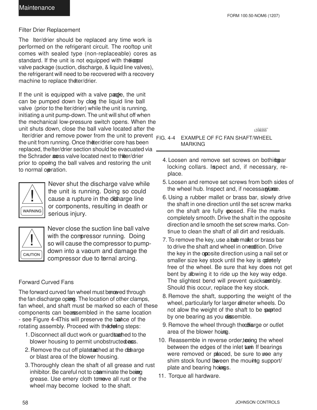
The forward curved fan wheel must be removed through the fan discharge opening. The location of other clamps, fan wheel, and shaft must be marked so each of these components can be reassembled in the same location
-see Figure
1.Disconnect all duct work or guards attached to the blower housing to permit unobstructed access.
2.Remove the cut off plate attached at the discharge or blast area of the blower housing.
3.Thoroughly clean the shaft of all grease and rust inhibitor. Be careful not to contaminate the bearing grease. Use emery cloth to remove all rust or the wheel may become “locked” to the shaft.
FORM
LD06355
LD06355
FIG. 4-4 – EXAMPLE OF FC FAN SHAFT/WHEEL MARKING
4.Loosen and remove set screws on both bearing locking collars. Inspect and, if necessary, re- place.
5.Loosen and remove set screws from both sides of the wheel hub. Inspect and, if necessary, replace.
6.Using a rubber mallet or brass bar, slowly drive the shaft in one direction until the set screw marks on the shaft are fully exposed. File the marks completely smooth. Drive the shaft in the opposite direction and file smooth the set screw marks. Con- tinue to clean the shaft of all dirt and residuals.
7.To remove the key, use a rubber mallet or brass bar to drive the shaft and wheel in one direction. Drive the key in the opposite direction using a nail set or smaller size key stock until the key is completely free of the wheel. Be sure that key does not get bent by allowing it to ride up the key way edge. The slightest bend will prevent quick assembly. Should this occur, replace the key stock.
8.Remove the shaft, supporting the weight of the wheel, particularly for larger diameter wheels. Do not allow the weight of the shaft to be supported by one bearing as you disassemble.
9.Remove the wheel through the discharge or outlet area of the blower housing.
10. Reassemble in reverse order, centering the wheel between the edges of the inlet venturi. If bearings were removed or replaced, be sure to reuse any shim stock found between the mounting support/ plate and bearing housings.
11. Torque all hardware.
58 | JOHNSON CONTROLS |