Installation
FORM
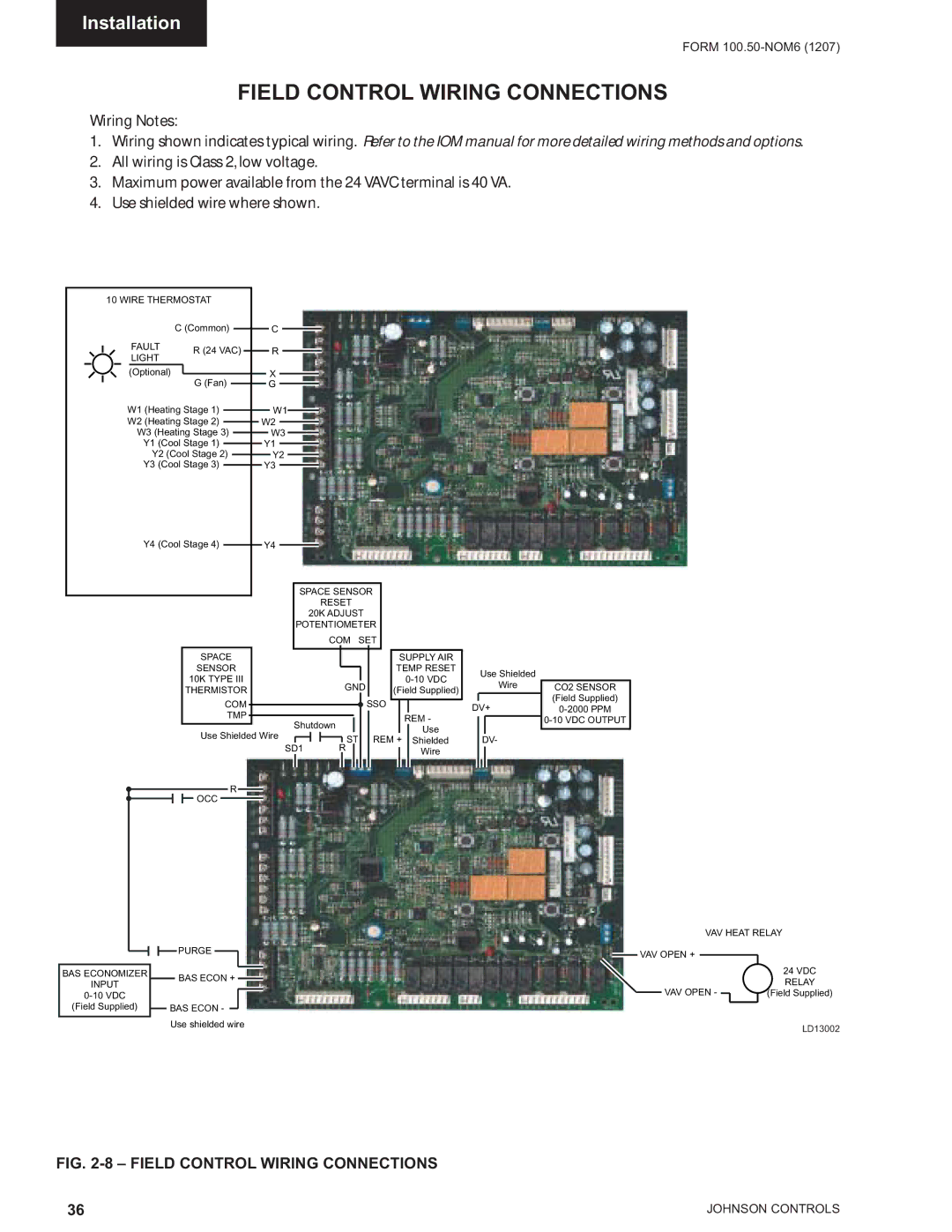
FIELD CONTROL WIRING CONNECTIONS
Wiring Notes:
1.Wiring shown indicates typical wiring. Refer to the IOM manual for more detailed wiring methods and options.
2.All wiring is Class 2, low voltage.
3.Maximum power available from the 24 VAVC terminal is 40 VA.
4.Use shielded wire where shown.
10 WIRE THERMOSTAT
C (Common)
FAULT | R (24 VAC) | ||
LIGHT | |||
| |||
(Optional) |
| G (Fan) | |
| |||
|
| ||
W1 (Heating Stage 1)
W2 (Heating Stage 2)
W3 (Heating Stage 3)
Y1 (Cool Stage 1)
Y2 (Cool Stage 2)
Y3 (Cool Stage 3)
Y4 (Cool Stage 4)
C
R
X
G
W1
W2
W3
Y1
Y2
Y3
Y4
SPACE SENSOR
RESET
20K ADJUST
POTENTIOMETER
| COM | SET |
|
| ||
SPACE |
|
| SUPPLY AIR |
| ||
SENSOR |
|
| TEMP RESET | Use Shielded | ||
10K TYPE III |
|
|
| |||
GND |
| Wire | ||||
THERMISTOR | (Field Supplied) | |||||
|
|
| ||||
COM |
|
| SSO |
| DV+ | |
TMP |
|
|
| REM - | ||
|
|
|
| |||
Shutdown |
|
|
| |||
|
| Use |
| |||
Use Shielded Wire | ST |
| REM + | DV- | ||
| Shielded | |||||
SD1 |
| |||||
R |
|
| Wire |
| ||
|
|
|
|
| ||
R |
|
|
|
|
| |
OCC |
|
|
|
|
| |
|
|
|
|
|
| PURGE |
|
|
|
|
|
|
|
|
|
|
|
|
|
BAS ECONOMIZER |
|
|
|
| BAS ECON + |
| |||
INPUT |
|
|
|
|
| ||||
|
|
|
|
|
|
|
| ||
|
|
|
|
|
|
|
| ||
(Field Supplied) |
|
| BAS ECON - |
|
| ||||
|
|
|
| ||||||
|
|
|
|
|
|
|
|
|
|
Use shielded wire
CO2 SENSOR
(Field Supplied)
VAV HEAT RELAY
![]() VAV OPEN +
VAV OPEN +
|
| 24 VDC |
VAV OPEN - |
| RELAY |
| (Field Supplied) | |
| ||
|
| LD13002 |
FIG. 2-8 – FIELD CONTROL WIRING CONNECTIONS
36 | JOHNSON CONTROLS |