Manuals
/
York
/
Household Appliance
/
Air Conditioner
York
YPAL 051, YPAL 061, YPAL 050, YPAL 060
manual
Fans
Models:
YPAL 060
YPAL 051
YPAL 050
YPAL 061
1
114
168
168
Download
168 pages
27.04 Kb
111
112
113
114
115
116
117
118
Troubleshooting
Install
Space Temperature Alarm
Fault Output
Safety Symbols
Power Wiring
Maintenance
Unit Configuration
Supply Air Temperature Reset
Cooling Setup
Page 114
Image 114
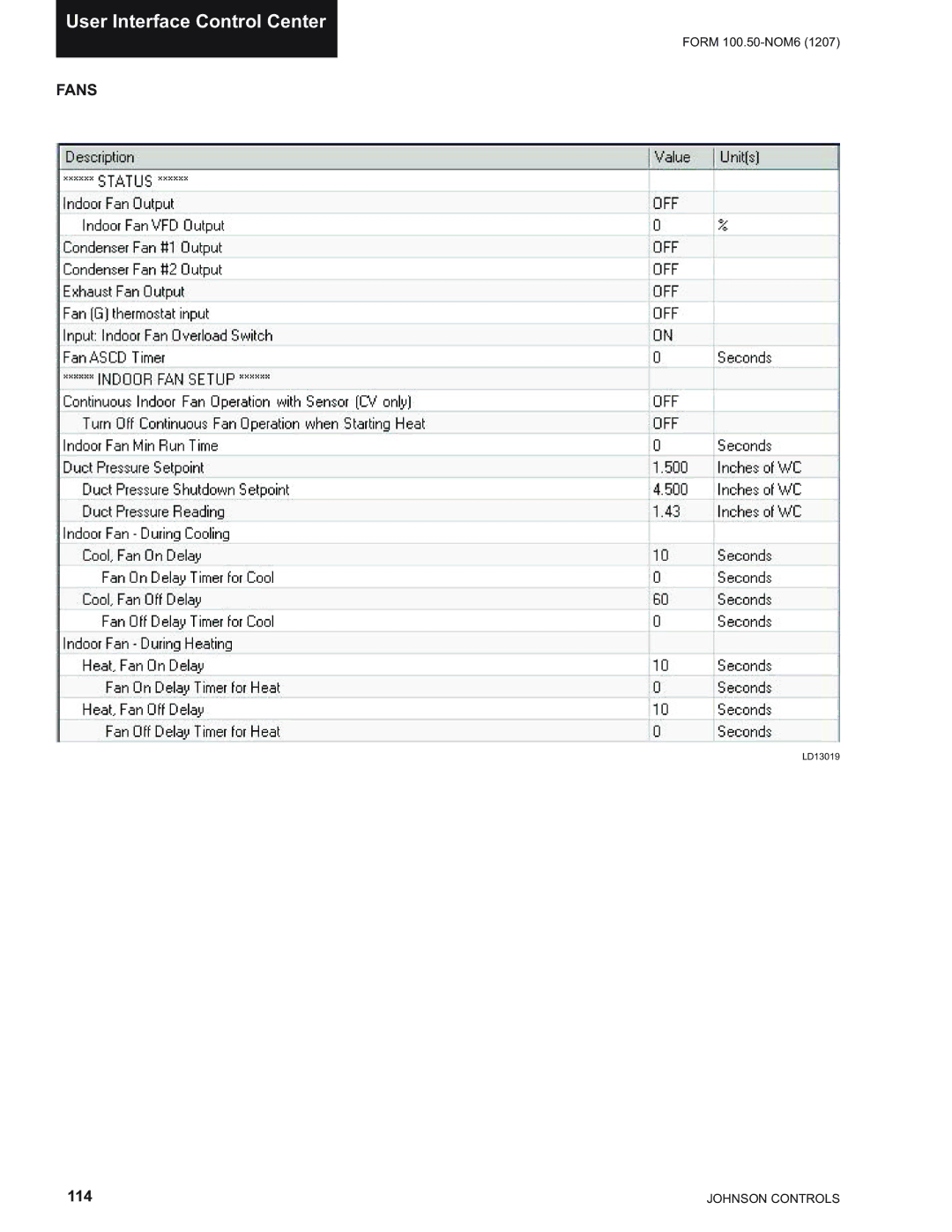
User Interface Control Center
FORM
100.50-NOM6
(1207)
FANS
LD13019
114
JOHNSON CONTROLS
Page 113
Page 115
Page 114
Image 114
Page 113
Page 115
Contents
INSTALLATION, Operation & Maintenance
Packaged Rooftop AIR Conditioning Units
Design Level F Simplicity Elite Control
General Safety Guidelines
Safety Symbols
Changeability of this Document
Nomenclature
Base Model Number
Table of Contents
Transducer Pneumatic Tubing
Field Control Wiring Connections
Checking the System Prior to Initial Start no Power
Sound and Vibration Transmission
GAS Heat Models
Sequence of Operation
Excessive SAT Supply AIR Temperature Control
Ventilation LOW Ambient Minimum Position Reset
104
154
List of Tables
19 Pipe Sizes
List of Figures
Packaged Rooftop AIR Conditioning Unit
Introduction
Introduction
Heating Section
AIR Management
Controls
Indoor AIR Quality
Service and Installation
Electrical
Installation
Location
Unit Clearances
Unit Rigging
Lifting LUG Locations
Unit Weights
Unit Weights 050-061 Models
Unit Center of Gravity
Unit Placement
Unit Corner Weights 050-061 Models
Roof Curb Installation
Physical Data
Physical Data 050-061 Models
Physical Data Compressors
Arrangement
General
Arrangement Drawing
Bottom Supply / Bottom
Arrangement
General Arrangement Drawing
Bottom Supply / Side Return
Arrangement Drawing
Bottom Supply / Rear Return
Curb Layout Drawing / 050-061 Models
Supply Return
Electrical Data
Electrical Service Sizing
Power Supply Voltage Limits
Load Definitions
Electric Data
Electric Data
Condensate Drain Piping
Thermostat
Fan input
Space Sensor
Occupied / Unoccupied Input
Fault Output
CO2 Sensor
Shutdown Input
VAV Heat Relay Output
Supply Air Temperature Reset
Dirty Filter Switch
Communication
Field Control Wiring Connections
Light
Overcurrent Protection Device Data is supplied on
Power Wiring
Power Wiring
Minimum CircuitAmpacity MCA is based on 125%
SINGLE-POINT Power Supply Wiring
SINGLE-POINT Power Supply Wiring
Line Earth Ground
DUAL-POINT Power Supply Wiring
11 DUAL-POINT Power Supply Wiring
Controls
Supply Single Point Dual Point TB Voltage Disconnect
Duct Static Transducer
Static Pressure Probe Installation
Static Pressure Control Plastic Tubing Pneumatic Tubing
Building Pressure Transducer
Filter Compartment Economizer
Unit Configuration
17 Supply AIR Duct Connection Configurations
18 Return AIR Duct Connection Configurations
Duct Connection Guidelines
GAS Piping
GAS Heating
Gas Piping Recommendations
19 Pipe Sizes
Combustion Vent
14 Combustion Vent
START-UP
Unit Checks
Crankcase Heaters
Startup
Unit Checks Power Applied
Verifying Compressor Rotation
Compressor Oil Level Check
Subcooling R-410A
Refrigerant Charge
Checking Superheat and Subcooling
Superheat R-410A
Leak Checking
R410-A Pressure / Temperature Chart
Psig Temp ˚F
Pre-Start Checks
Post Start Checks
GAS Heat Models
Type Line Pressure Manifold Pressure
LOW Fire / High Fire Pressures
GAS Heat Performance Data
GAS
Maintenance
Belt Tension
Condenser Coils
Motor Bearing Lubrication
Entire Unit Inspection
Belt Replacement
Belt Tensioning
Filter Drier Replacement
Forward Curved Fans
Fan Motor
Fan Shaft Bearings
Mounting Details
Eccentric Type
Bearing Lock Devices
Torquing of Set-screws
This page Intentionally Left Blank
Sequence of Operation
Occupied / Unoccupied Mode
Constant Volume Mode CV
Unit Type
Occupied Cooling
Heating Mode Enabled for Operation
Thermostat Input
Unoccupied Cooling
Unoccupied Heating
Space Sensor Hard Wired or Communicated
Occupied Heating
Cooling Operation Occupied or Unoccupied
Heating Operation Occupied or Unoccupied
Stand Alone
Simplicity Control will stage off the cooling as follows
Variable AIR Volume VAV
Cooling Occupied with Thermostat
Cooling Supply AIR Temp Lower Setpoint
Cooling Unoccupied with Thermostat
Occupied or Unoccupied Heating with a Thermo- stat
VAV Occupied Heating Setpoint
Morning Warm UP / VAV Return AIR Temp Setpoint
Morning Warm UP RAT Setpoint
VAV Supplyair Temp Reset Setpoint
Occupied Cooling Stand Alone
Heating Unoccupied Stand Alone
Cooling Unoccupied Stand Alone
Heating Occupied Stand Alone
Sequence of Operation
Operation and Pressure Control Range
Configuration Jumpers and Potentiometers
Constant Volume CV
Supply FAN Operation
Variable Air Volume VAV
Dry Bulb
VAV Supply Fan Speed Control
Duct Pressure Shutdown Setpoint
Able Setpoint
Single Enthalpy
Outside AIR Humidity Sensor Installed
Return AIR Humidity Sensor Installed
Dual Enthalpy
Constant Volume Economizer Set Point
Variable Air Volume Economizer Set Point
Economizer / Compressor Operation
Economizer PI Loop Proportional and Integral
Economizer Loading
Constant Volume
Variable Air Volume
Compressor on When Space Input Satisfied
Comfort Ventilation
Operation During OFF Cycle
Cooling
Tion Upper Setpoint
Conditions of Operation
Supply AIR Temp Limit Cooling Setpoint
Heating
Supply AIR Temp Limit Heating Setpoint
Space Sensor with SET Point Adjustment
Space Sensor Fault Override Enable
Remote Control
Redline
Metric Operation
Loadshed
Dirty Filter
INTELLI-START
First day of heating or cooling operation
Subsequent Operation
ING WARM-UP/VAV Return AIR Temp Setpoint
Morning WARM-UP
Hydronic Heat
Hydronic Heat Freeze Stat
Ventilation
Manual
Fixed Minimum
Demand Ventilation
Ventilation LOW Ambient Minimum Position Reset
Definitions
On/Off Control Based on Outdoor Damper Posi- tion
On/Off Control Based on Building Pressure
Exhaust FAN Operation
Modulating Damper with Fixed Speed Exhaust
Modulating Exhaust with a VFD
Criteria for Operation
PRE-OCCUPANCY Purge
LOW Voltage Protection
Energy Recovery Ventilator
Space Temperature Alarm
Outdoor AIR Heating Lockout
SAT Alarm for Heating
Economizer Minimum Position Alarm
Supply AIR Temp Alarm Setpoint for Heating
SAT Alarm for Cooling
Supply AIR Temp Alarm Setpoint for Cooling
Alarm History
User Interface
Unit Controller Interface
Program Button
ADDRESS/DOWN Button
ALARM/CHANGE
TEST/UP Button
Character Display Addresses & Codes
Parameter Points List
102
103
Simplicity PC Download
Left click on software
USB Adapter Drive Simplicity Pocket PC
Cable Wire Color Adapter Terminal Board Marking
Establishing Communication
108
Left-click on the particular Simplicity device de- sired
110
Equipment Installation
Simplicity PC Data Screens
Device Names
Sensor Readings
ECONOMIZER/EXHAUST
Fans
Cooling Setup
Cooling Status
Heating Setup
Heating Status
System Options
OUTPUTS/STATUS
Inputs
COMFORT/DEMAND Ventilation
Graphic
Weekly Schedule Settings
Weekly Schedule
Holiday Schedule
Holiday Schedule
Alarms
Revising Settings
127
128
129
HEX DEC Value
Initial Address BIT Default
Simplicity Elite Data MAP
HEX
Description HEX DEC Value
132
133
134
135
136
137
138
139
140
Parameter Descriptions and Options
Definitions
Parameter Description and Options
143
144
145
146
147
148
149
150
151
152
Temperature Sensor Resistance
Service
Temperature Sensors
Analog Input Operation
Duct Pressure Transducer
Return Fan Pressure Transducer
Discharge Pressure Transducer
Return FAN Pressure Transducer Output
Pressure Transducers
Suction Pressure Transducer
Humidity Sensors
Humidity Sensor Outputs
Furnace Status Input
CO2 Sensor Output
PPM CO2 Output
Connector Locations Wiring Data
Connector # Type Identification Wire # Description
158
159
Faults and Lockouts
Light Emitting Diode Alarm Codes
Alarm Code Descriptions
Alarm Code Description
162
Alarm Trouble Shooting
Gas Heating Alarms 16, 17
Low Pressure Cutout Alarm 09, 10, 11
Limit Switch Alarms 13, 14
Space Temperature Sensor Alarm
Outdoor Air Temperature Sensor Alarm
Supply Air Temperature Sensor Alarm
Return Air Temperature Sensor Alarm
Dirty Filter Switch Alarm
IAQ CO2 Sensor Alarm
Outdoor Humidity Sensor Alarm
Return Humidity Sensor Alarm
Time Clock Error Alarm
Space Temperature Trending Alarm
Supply Air Temperature Cooling Alarm
Supply Air Temperature Heating Alarm
Duct Static Low Pressure Alarm
ALL Rights Reserved
Top
Page
Image
Contents