Installation
FORM
•Also avoid locations beneath windows or be- tween structures.
•Optional condenser coil protection should be used for seashore locations or other harsh environ- ments.
•The unit should be installed on a roof that is structur- ally strong enough to support the weight of the unit with a minimum of deflection. It is recommended that the unit(s) be installed not more than 15 feet from a main support beam to provide proper structural support and to minimize the transmis- sion of sound and vibration. Ideally, the center of gravity should be located over a structural support or building column.
•Location of unit(s) should also be away from building flue stacks or exhaust ventilators to prevent possible reintroduction of contaminated air through the outside air intakes.
•Be sure the supporting structures will not obstruct the duct, gas or wiring connections.
LOCATION
Of the many factors that can effect the location of equipment, some of the most important to consider are Structural, Acoustical and Service clearances. Proper attention should be made at the design stage to ensure proper structural support. In cases where equipment is being replaced, be aware of building design to insure support is adequate for the application.
The next most important consideration in applying roof top equipment is that of sound from the equipment. Special care should be made to keep the roof top unit
away from sound sensitive areas such as conference rooms, auditoriums and executive offices and any other room that may have potential for tenant occupancy. Possible locations could be above hallways, mechanical or utility rooms.
Finally, service clearances should be maintained in rooftop design to insure safe access to the unit. Unit clearances are designed so that technicians have enough space between units, building walls, and edges of building to gain access safely. In cases where space is limited, please call your local York representative for additional information.
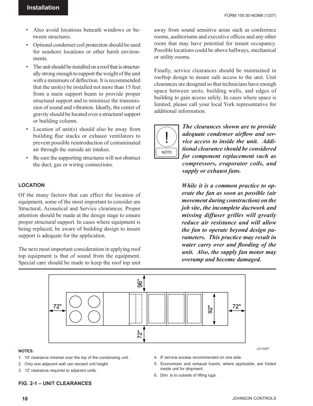
The clearances shown are to provide adequate condenser airflow and ser- vice access to inside the unit. Addi- tional clearance should be considered for component replacement such as compressors, evaporator coils, and supply or exhaust fans.
While it is a common practice to op- erate the fan as soon as possible (air movement during construction) on the job site, the incomplete ductwork and missing diffuser grilles will greatly reduce air resistance and will allow the fan to operate beyond design pa- rameters. This practice may result in water carry over and flooding of the unit. Also, the supply fan motor may overamp and become damaged.
96" |
NOTES:
1. 10' clearance minimal over the top of the condensing unit.
2. Only one adjacent wall can exceed unit height.
3. 12' clearance required to adjacent units.
LD13267
4. 8' service access recommended on one side.
5. Economizer and exhaust hoods, where applicable, are folded inside unit for shipment.
6. Dim. is to outside of lifting lugs.
FIG. 2-1 – UNIT CLEARANCES
18 | JOHNSON CONTROLS |