FORM
SECTION 8 – SERVICE
ANALOG INPUT OPERATION | Duct Pressure Transducer |
This section describes the control operation of the (29)
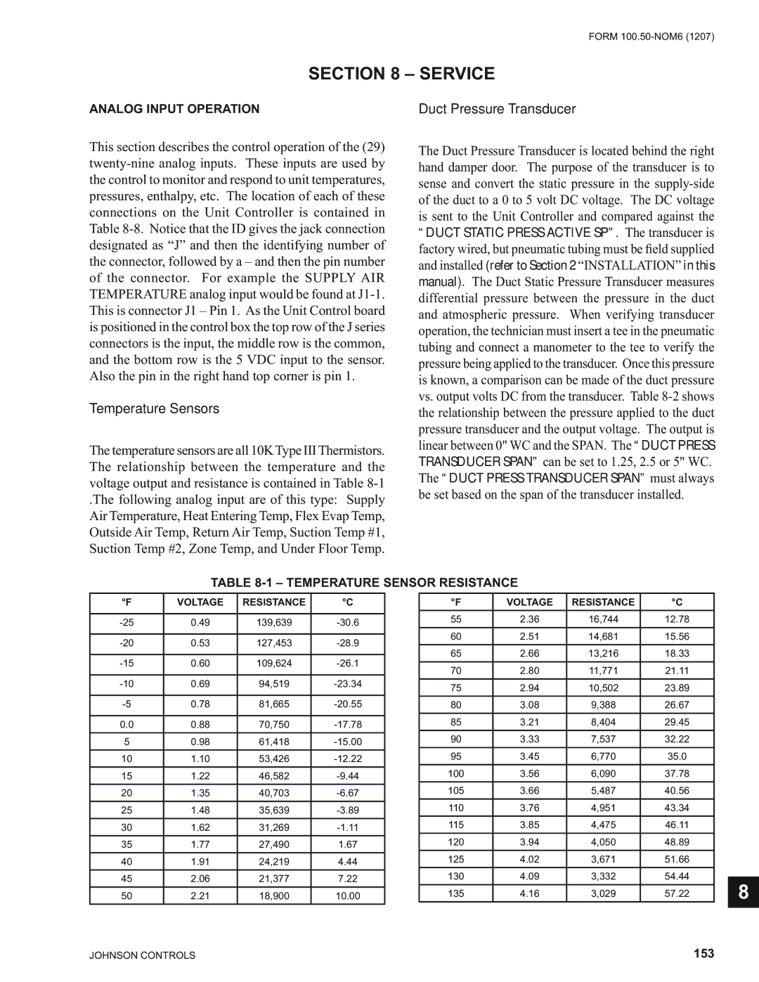
Temperature Sensors
The temperature sensors are all 10KType IIIThermistors. The relationship between the temperature and the voltage output and resistance is contained in Table
.The following analog input are of this type: Supply Air Temperature, Heat Entering Temp, Flex Evap Temp, Outside Air Temp, Return Air Temp, Suction Temp #1, Suction Temp #2, Zone Temp, and Under Floor Temp.
The Duct Pressure Transducer is located behind the right hand damper door. The purpose of the transducer is to sense and convert the static pressure in the
TABLE 8-1 – TEMPERATURE SENSOR RESISTANCE
°F | VOLTAGE | RESISTANCE | °C |
| °F | VOLTAGE | RESISTANCE | °C |
|
| |
|
|
|
|
| 55 | 2.36 | 16,744 | 12.78 |
|
| |
0.49 | 139,639 |
| |||||||||
|
|
|
|
| 60 | 2.51 | 14,681 | 15.56 |
|
| |
0.53 | 127,453 |
| |||||||||
| 65 | 2.66 | 13,216 | 18.33 |
|
| |||||
|
|
|
|
|
|
| |||||
0.60 | 109,624 |
| |||||||||
| 70 | 2.80 | 11,771 | 21.11 |
|
| |||||
|
|
|
|
|
|
| |||||
0.69 | 94,519 |
|
|
|
|
|
|
| |||
| 75 | 2.94 | 10,502 | 23.89 |
|
| |||||
|
|
|
|
|
|
| |||||
0.78 | 81,665 |
| 80 | 3.08 | 9,388 | 26.67 |
|
| |||
|
|
|
|
| 85 | 3.21 | 8,404 | 29.45 |
|
| |
0.0 | 0.88 | 70,750 |
|
|
| ||||||
|
|
|
|
| 90 | 3.33 | 7,537 | 32.22 |
|
| |
5 | 0.98 | 61,418 |
|
|
| ||||||
|
|
|
|
| 95 | 3.45 | 6,770 | 35.0 |
|
| |
10 | 1.10 | 53,426 |
|
|
| ||||||
|
|
|
|
| 100 | 3.56 | 6,090 | 37.78 |
|
| |
15 | 1.22 | 46,582 |
|
|
| ||||||
|
|
|
|
| 105 | 3.66 | 5,487 | 40.56 |
|
| |
20 | 1.35 | 40,703 |
|
|
| ||||||
|
|
|
|
| 110 | 3.76 | 4,951 | 43.34 |
|
| |
25 | 1.48 | 35,639 |
|
|
| ||||||
|
|
|
|
| 115 | 3.85 | 4,475 | 46.11 |
|
| |
30 | 1.62 | 31,269 |
|
|
| ||||||
|
|
|
|
| 120 | 3.94 | 4,050 | 48.89 |
|
| |
35 | 1.77 | 27,490 | 1.67 |
|
|
| |||||
|
|
|
|
| 125 | 4.02 | 3,671 | 51.66 |
|
| |
40 | 1.91 | 24,219 | 4.44 |
|
|
| |||||
|
|
|
|
| 130 | 4.09 | 3,332 | 54.44 |
|
| |
45 | 2.06 | 21,377 | 7.22 |
|
|
| |||||
8 | |||||||||||
|
|
|
|
| 135 | 4.16 | 3,029 | 57.22 |
| ||
50 | 2.21 | 18,900 | 10.00 |
|
| ||||||
|
|
|
|
|
|
|
|
|
|
| |
|
|
|
|
|
|
|
|
|
|
|
JOHNSON CONTROLS | 153 |