Installation
DUCT SYSTEM
Duct Connection Guidelines
All intake and discharge air duct connection to the unit may be made directly to the unit. These air duct connections should be on flexible material and should be installed so they are sufficiently loose. Duct runs and transitions must be made carefully to hold friction loss to a minimum. Avoid short turns, and duct elbows should contain splitters or turning vanes.
Duct work connected to the fan discharge should run in a straight line for at least two equivalent outlet diameters. Never deadhead the discharge into the flat surface of a plenum.
Refer to Table
TABLE 2-17 – SUPPLY AIR DUCT CONNECTION
CONFIGURATIONS
UNIT CONFIGURATION | SUPPLY AIR |
| |||
|
|
|
| ||
BOTTOM | LEFT |
| RIGHT | ||
|
|
| |||
|
|
|
|
|
|
| COOLING ONLY | √ | √ |
| √ |
|
|
|
|
|
|
COOL/GAS HEAT | √ | √ |
| N/A | |
MBH |
| ||||
|
|
|
|
| |
|
|
|
|
|
|
| COOL/GAS HEAT 1125 MBH | √ | N/A |
| N/A |
TABLE 2-18 – RETURN AIR DUCT CONNECTION
CONFIGURATIONS
UNIT CONFIGURATION | SUPPLY AIR |
| |||
BOTTOM | LEFT |
| RIGHT | ||
|
|
| |||
|
|
|
|
|
|
| NO EXHAUST | √ | √ |
| √ |
| BAROMETRIC RELIEF | √ | √ |
| N/A |
DAMPER |
| ||||
|
|
|
| ||
| POWERED EXHAUST FAN | √ | √ |
| N/A |
|
|
|
|
|
|
| RETURN FAN | √ | N/A |
| N/A |
FORM
Installation of elbows, discharge damper and other abrupt flow area changes installed directly at the fan outlet will cause system losses. These losses must be taken into account during the design phase and must be added to any field measurements.
SOUND AND VIBRATION TRANSMISSION
All roof mounted air handling units generate some sound and vibration, which may or may not require some special treatment of the air conditioned space. The noise generated by the air handling unit is dependent on the speed of the fan, the amount of air the fan is moving, the fan type and the static efficiency of the fan. In applications where sound and vibration transmissions may be objectionable, good acoustical engineering practices must be incorporated in the system design.
The eco2 unit is designed for lower sound levels than competitive units by using flexible fan connections, fan spring isolators,
Even with these equipment design features, the acoustical characteristics of the entire installation must never be overlooked.Additional steps for the acoustical characteristics of a rooftop installation should be addressed during the design phase of a project to avoid costly alterations after the installation of the equipment. During the design phase of a project, the designing engineer should consider, at a minimum, the impact of the equipment location, rooftop installation, building structure, and duct work.
Discharge | Return |
RIGHT
FRONT | FRONT |
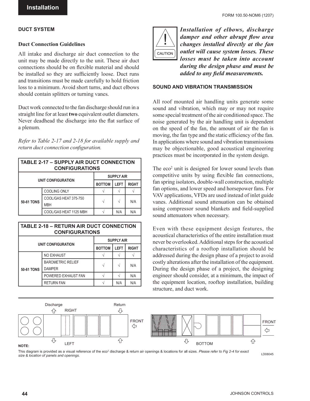
NOTE: | LEFT | BOTTOM |
|
| |
This diagram is provided as a visual reference of the eco2 discharge & return air openings & locations for all sizes. Please refer to Fig | ||
size & location of panels and openings. | LD08045 | |
44 | JOHNSON CONTROLS |