26 | FIG. |
|
|
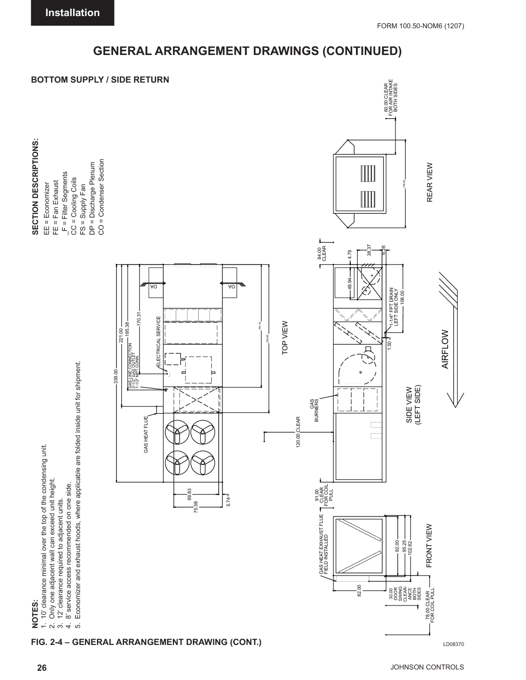
NOTES:
1.10’ clearance minimal over the top of the condensing unit.
2.Only one adjacent wall can exceed unit height.
3.12’ clearance required to adjacent units.
4.8’ service access recommended on one side.
5.Economizer and exhaust hoods, where applicable are folded inside unit for shipment.
339.00
|
| 221.00 |
| |
|
|
| 195.38 | |
GAS LINE CONNECTION |
| |||
|
|
| ||
|
|
| ||
|
| 170.31 | ||
|
|
| ||
GAS HEAT FLUE
ELECTRICAL SERVICE
69.83
75.58
5.74
191.19
230.62
OA
OA
SECTION DESCRIPTIONS:
EE= Economizer FE = Fan Exhaust _F = Filter Segments CC = Cooling Coils FS = Supply Fan
DP = Discharge Plenum CO = Condenser Section
BOTTOM SUPPLY / SIDE RETURN
GENERAL | Installation |
| |
ARRANGEMENT |
|
|
| TOP VIEW |
|
|
| 120.00 CLEAR |
|
|
| GAS |
|
GAS HEAT EXHAUST FLUE | 91.00 | BURNERS | 84.00 |
CLEAR |
| ||
| CLEAR | ||
FIELD INSTALLED | FOR COIL |
| |
|
| ||
| PULL |
|
|
|
| 49.94 | 4.79 |
DRAWINGS |
82.00
30.00
DOOR
SWING CLEAR- ANCE BOTH SIDES
78.00CLEAR
FOR COIL PULL
92.00
95.25
102.62
FRONT VIEW
38.37
6.28
1.50
106.00
SIDE VIEW (LEFT SIDE)
60.00 CLEAR
FOR AIR INTAKE
BOTH SIDES
136.82
REAR VIEW
(CONTINUED) | FORM 100 |
|
AIRFLOW
(1207) |