FORM
TABLE 4-2 – SET SCREW TORQUE
SET | HEX. SIZE | MIN. RECOMMENDED | ||
SCREW | ACROSS |
| TORQUE | |
DIA. | FLATS | INCH | FOOT | |
| LBS. | |||
| LBS. | LBS. | ||
|
| |||
1/4 1/8 | 66 - 85 | 5.5 | - 7.2 |
|
5/16 | 5/32 | 126 | - 164 | 10.5 - 13.7 |
3/8 3/16 | 228 - 296 | 19.0 | - 24.7 |
|
7/16 | 7/32 | 348 | - 452 | 29.0 - 37.7 |
1/2 1/4 | 504 - 655 42.0 | - 54.6 |
| |
5/8 5/16 | 1104 - 1435 | 92.0 - 119.6 |
| |
Torquing of Set-screws
1. Torque screw “A” to 1/2 recommended torque.
2. Torque screw “B” to full min. recommended value.
3. Torque screw “A” to full recommended value.
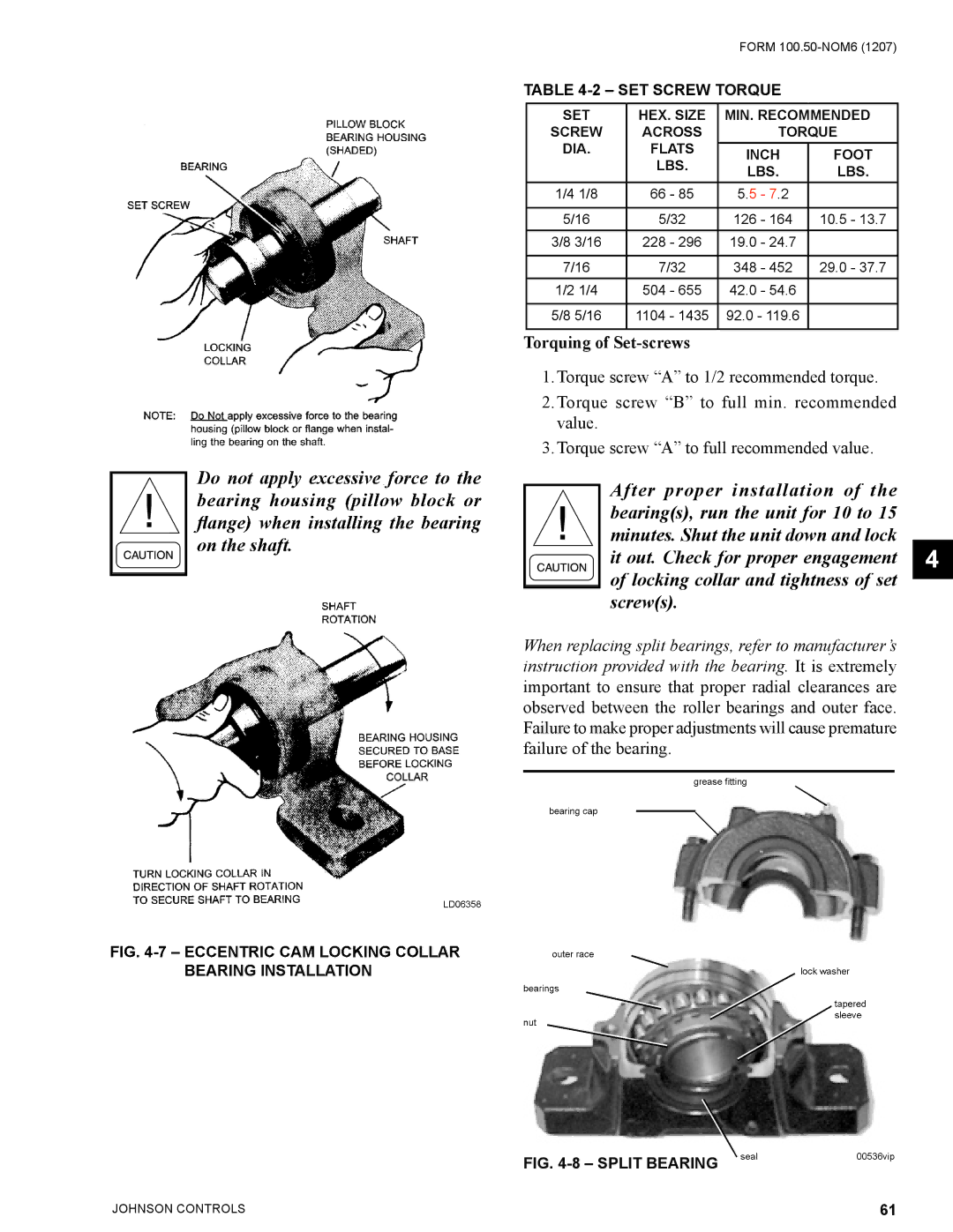
After proper installation of the bearing(s), run the unit for 10 to 15 minutes. Shut the unit down and lock
it out. Check for proper engagement 4 of locking collar and tightness of set screw(s).
When replacing split bearings, refer to manufacturer’s instruction provided with the bearing. It is extremely important to ensure that proper radial clearances are observed between the roller bearings and outer face. Failure to make proper adjustments will cause premature failure of the bearing.
grease fi tting
BEARING INSTALLATION
FIG. | seal | 00536vip |
|
|
JOHNSON CONTROLS | 61 |