FORM
GAS HEATING
GAS PIPING
Proper sizing of the gas piping depends on the cubic feet per hour of gas flow required, specific gravity of the gas and the length of run. National Fuel Gas Code Z223.1
–latest Edition should be followed in all cases unless superseded by local codes or gas company requirements. Refer to Table
The heating value of the gas may differ with locality. The value should be checked with the local gas utility.
TABLE 2-19 – PIPE SIZES
LENGTH IN | NOMINAL IRON PIPE SIZE | |
FEET |
| 2 IN.1 |
10 | 1,600 | 3,050 |
20 | 1,100 | 2,100 |
30 | 890 | 1,650 |
40 | 760 | 1,450 |
50 |
| 1,270 |
60 |
| 1,150 |
70 |
| 1,050 |
80 |
| 990 |
| FACTORY |
|
|
|
|
|
|
|
|
|
|
| UNIT BASERAIL |
|
|
|
|
| |||||||||||
PIPING |
|
|
|
|
|
|
|
|
|
| UNION (For Servicing) |
|
|
| |||||||||||||||
|
|
|
|
|
|
|
|
|
|
|
|
|
|
|
|
|
|
|
|
| |||||||||
|
|
|
|
|
|
|
|
|
|
|
|
|
|
|
|
|
|
| 1/8" | NPT PLUG |
|
|
|
| |||||
|
|
|
|
|
|
|
|
|
|
|
|
|
|
|
|
|
|
|
|
|
|
| |||||||
|
|
|
|
|
|
|
|
|
|
|
|
|
|
|
|
|
|
|
|
|
|
| MANUAL GAS |
|
| ||||
|
|
|
|
|
|
|
|
|
|
|
|
|
|
|
|
|
|
|
|
|
|
|
|
| |||||
|
|
|
|
|
|
|
|
|
|
|
|
|
|
|
|
|
|
|
|
|
|
|
|
| |||||
|
|
|
|
|
|
|
|
|
|
|
|
|
|
|
|
|
|
|
|
|
|
|
|
| |||||
|
|
|
|
|
|
|
|
|
|
|
|
|
|
|
|
|
|
|
|
|
|
|
|
| |||||
|
|
|
|
|
|
|
|
|
|
|
|
|
|
|
|
|
|
|
|
|
|
|
|
| |||||
|
|
|
|
|
|
|
|
|
|
|
|
|
|
|
|
|
|
|
|
|
|
|
|
| |||||
FPT |
|
|
|
|
|
|
|
|
|
|
|
|
|
|
|
|
| ||||||||||||
|
|
|
|
|
|
|
|
|
|
|
|
|
|
| VALVE |
|
|
|
|
| |||||||||
|
|
|
|
|
|
|
|
|
|
|
|
|
|
|
|
|
|
|
|
|
|
|
|
|
|
|
| ||
| ROOF |
|
|
|
|
|
|
|
|
|
|
|
|
|
|
|
|
|
|
|
|
|
|
|
|
| |||
|
|
|
|
|
|
|
|
|
|
|
|
|
|
|
|
|
|
|
|
|
|
|
|
|
|
|
| ||
|
|
|
|
|
|
|
|
|
|
|
|
|
|
|
|
|
|
|
|
|
|
|
|
|
|
| |||
|
|
|
|
|
|
|
|
|
|
|
|
|
|
|
|
|
|
|
|
|
|
|
|
|
|
| |||
|
|
|
|
| PITCH POCKET | 2 | |||||||||||||||||||||||
| CURB |
|
|
|
|
|
|
|
| DRIP LEG |
|
|
|
|
| ||||||||||||||
|
|
|
|
|
|
|
|
|
|
|
|
|
| ||||||||||||||||
|
|
|
|
|
|
|
|
|
|
|
|
|
|
|
|
|
|
| LD11765A | ||||||||||
|
|
|
|
|
|
|
|
|
|
|
|
|
|
|
|
|
|
| |||||||||||
|
|
|
|
|
|
|
|
|
|
|
|
|
|
|
|
|
|
| |||||||||||
|
|
|
|
|
|
|
|
|
|
|
|
|
|
|
|
|
|
|
|
|
|
|
|
| |||||
|
|
|
|
|
|
|
|
|
|
|
|
|
|
|
|
|
|
|
|
|
|
|
|
|
| ||||
|
|
|
|
|
|
|
|
|
|
|
|
|
|
|
|
|
|
|
|
|
|
|
|
|
| ||||
|
|
|
|
|
|
|
|
|
|
|
|
|
|
|
|
|
|
|
|
|
| ROOF |
|
| |||||
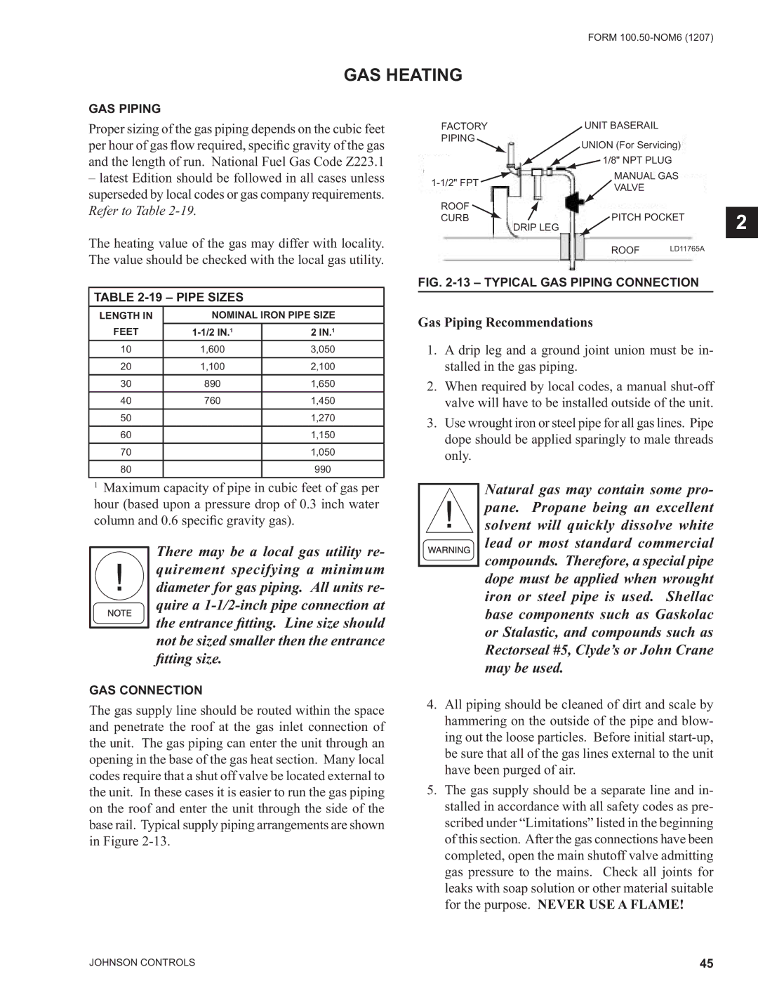
FIG. 2-13 – TYPICAL GAS PIPING CONNECTION
Gas Piping Recommendations
1.A drip leg and a ground joint union must be in- stalled in the gas piping.
2.When required by local codes, a manual
3.Use wrought iron or steel pipe for all gas lines. Pipe dope should be applied sparingly to male threads only.
1Maximum capacity of pipe in cubic feet of gas per hour (based upon a pressure drop of 0.3 inch water column and 0.6 specific gravity gas).
There may be a local gas utility re- quirement specifying a minimum diameter for gas piping. All units re- quire a
GAS CONNECTION
Natural gas may contain some pro- pane. Propane being an excellent solvent will quickly dissolve white lead or most standard commercial compounds. Therefore, a special pipe dope must be applied when wrought iron or steel pipe is used. Shellac base components such as Gaskolac or Stalastic, and compounds such as Rectorseal #5, Clyde’s or John Crane may be used.
The gas supply line should be routed within the space and penetrate the roof at the gas inlet connection of the unit. The gas piping can enter the unit through an opening in the base of the gas heat section. Many local codes require that a shut off valve be located external to the unit. In these cases it is easier to run the gas piping on the roof and enter the unit through the side of the base rail. Typical supply piping arrangements are shown in Figure
4.All piping should be cleaned of dirt and scale by hammering on the outside of the pipe and blow- ing out the loose particles. Before initial
5.The gas supply should be a separate line and in- stalled in accordance with all safety codes as pre- scribed under “Limitations” listed in the beginning of this section. After the gas connections have been completed, open the main shutoff valve admitting gas pressure to the mains. Check all joints for leaks with soap solution or other material suitable for the purpose. NEVER USE A FLAME!
JOHNSON CONTROLS | 45 |