Whenever a displacement switch is tripped, t h e m a c h i n e s t o p s a n d r e d i s t r i b u t e s t h e clothes load. This involves a three (3) second pause, followed by a five (5) second reverse tumble
(3)seconds, then start the distribution profile again. To redistribute the load, the machine tumbles the load
twice | as | the washer attempts to spin at | 800 |
r p m . |
|
|
|
Once | the | load is properly redistributed | and |
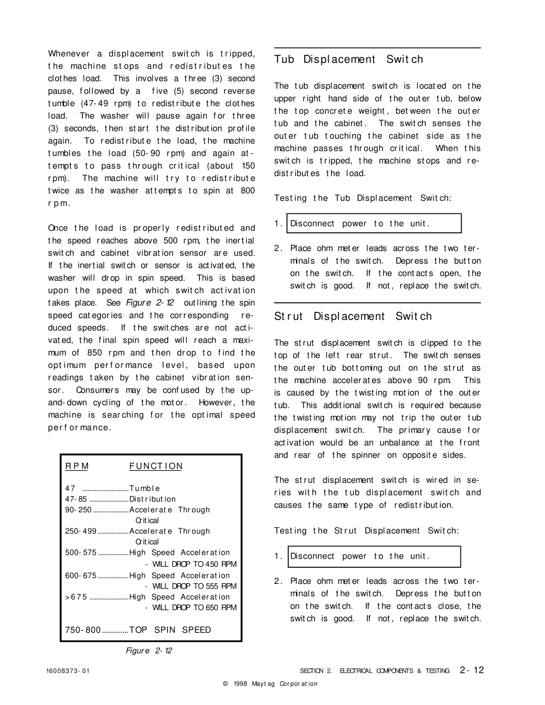
the speed reaches above 500 rpm, the inertial switch and cabinet vibration sensor are used. If the inertial switch or sensor is activated, the washer will drop in spin speed. This is based upon the speed at which switch activation takes place. See Figure
machine is | searching for the optimal speed | |
p e r f o r m a n c e . |
| |
R P M | F U N C T I O N | |
4 7 | T u m b l e |
|
Distribution |
| |
Accelerate | Through | |
| Critical |
|
Accelerate | Through | |
| Critical |
|
High Speed | Acceleration | |
-WILL DROP TO 450 RPM
-WILL DROP TO 555 RPM
> 6 7 5 ....................... High Speed Acceleration
- WILL DROP TO 650 RPM
Figure
1 6 0 0 8 3 7 3 - 0 1
Tub Displacement Switch
The tub displacement switch is located on the upper right hand side of the outer tub, below the top concrete weight, between the outer tub and the cabinet. The switch senses the outer tub touching the cabinet side as the machine passes through critical. When this switch is tripped, the machine stops and re- distributes the load.
Testing the Tub Displacement Switch:
1 . Disconnect power to the unit.
2 . Place ohm meter leads across the two ter- minals of the switch. Depress the button on the switch. If the contacts open, the switch is good. If not, replace the switch.
Strut Displacement Switch
The strut displacement switch is clipped to the top of the left rear strut. The switch senses the outer tub bottoming out on the strut as the machine accelerates above 90 rpm. This is caused by the twisting motion of the outer tub. This additional switch is required because the twisting motion may not trip the outer tub displacement switch. The primary cause for activation would be an unbalance at the front and rear of the spinner on opposite sides.
The strut displacement switch is wired in se- ries with the tub displacement switch and causes the same type of redistribution.
Testing the Strut Displacement Switch:
1 . Disconnect power to the unit.
2 . Place ohm meter leads across the two ter- minals of the switch. Depress the button on the switch. If the contacts close, the switch is good. If not, replace the switch.
SECTION 2. ELECTRICAL COMPONENTS & TESTING | 2 - 1 2 |
© 1998 Maytag Corporation