DRIVE MOTOR
The drive motor is a switched reluctance type motor. The basic operating principle of the switched reluctance motor is direct magnetic attraction between the stationary electromag- netic coils (stator) and a specially configured rotor or armature (Figure
Figure
Multiple stator coils are positioned around the rotor and are connected in three different phased "sets" of paired coils.
Magnetic attraction causes the rotor poles to turn toward the coils. The electronic motor control board switches the magnetic field off as the rotor pole piece approaches; then, turns on another set of coils further ahead. It is this switching action of motor phases that determines direction and rotational speed of the rotor (and shaft). The motor control board changes the 120 VAC voltage line input to 170 VDC, and distributes the current phases to the stator coil sets in sequence to the drive motor.
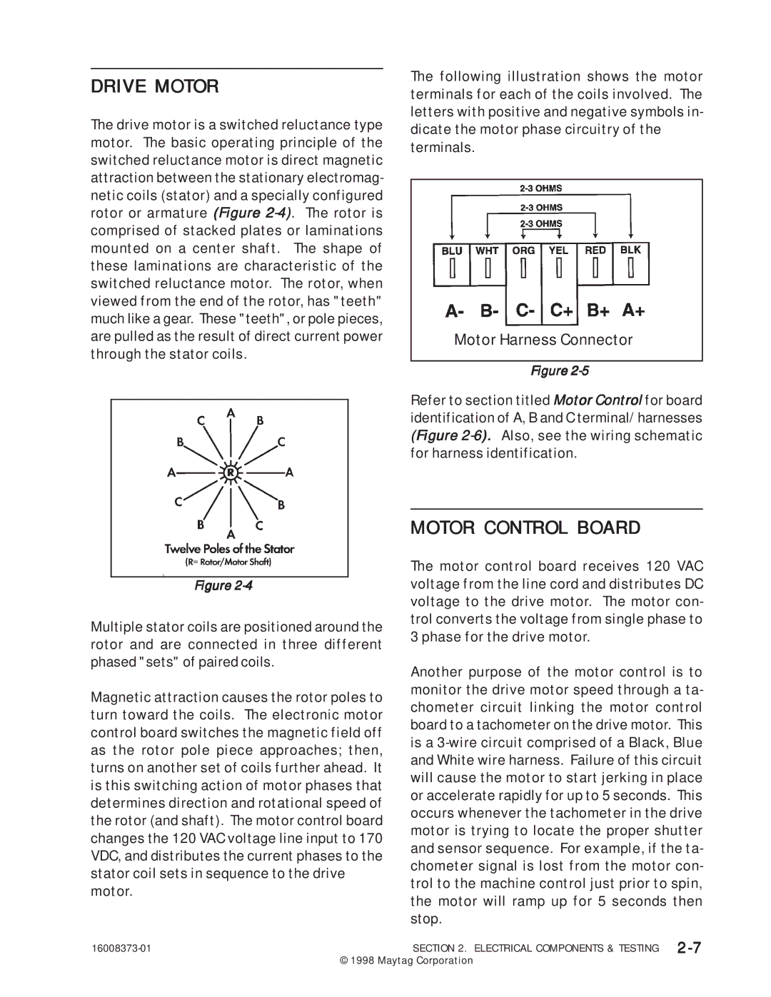
The following illustration shows the motor terminals for each of the coils involved. The letters with positive and negative symbols in- dicate the motor phase circuitry of the terminals.
Motor Harness Connector
Figure
Refer to section titled Motor Control for board identification of A, B and C terminal/harnesses (Figure
MOTOR CONTROL BOARD
The motor control board receives 120 VAC voltage from the line cord and distributes DC voltage to the drive motor. The motor con- trol converts the voltage from single phase to 3 phase for the drive motor.
Another purpose of the motor control is to monitor the drive motor speed through a ta- chometer circuit linking the motor control board to a tachometer on the drive motor. This is a
SECTION 2. ELECTRICAL COMPONENTS & TESTING | |
| © 1998 Maytag Corporation |