TOP COVER
R E M O V A L
1.Remove the front panel (See Front Panel Removal).
2.Remove the four screws fastening the dis- penser bezel to the top of the top cover (See Dispenser Assembly).
3.Remove two 5/16" hex head screws secur- ing the two hold down brackets on the top cover (Figure
4.To remove the hold down brackets, swing the bracket to the outside to unhook the bracket from the slot in the top cover lip
5.If the door is still positioned on the front shroud, open the door prior to lifting the front of the top cover and tilt the top cover toward the rear of the machine.
Figure | Figure |
DOOR LOCK MECHANISM
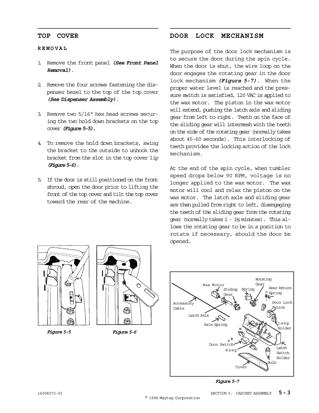
The purpose of the door lock mechanism is to secure the door during the spin cycle. When the door is shut, the wire loop on the door engages the rotating gear in the door lock mechanism (Figure
At the end of the spin cycle, when tumbler speed drops below 90 RPM, voltage is no longer applied to the wax motor. The wax motor will cool and relax the piston on the wax motor. The latch axle and sliding gear are then pulled from right to left, disengaging the teeth of the sliding gear from the rotating gear (normally takes 1 - 1½ minutes). This al- lows the rotating gear to be in a position to rotate if necessary, should the door be opened.
|
| Rotating | |
Wax Motor |
| Gear | |
Sliding | Spring | Gear Return | |
Spring | |||
Gear |
| ||
|
| ||
Accessory |
| Door Lock | |
Cable |
| Switch |
Latch Axle
Axle Spring | Lamp | |
Holder | ||
| ||
Door Switch | Latch | |
Ramp | ||
Switch | ||
| ||
| Holder | |
| Bulb | |
Cover |
|
| Figure |
SECTION 5. CABINET ASSEMBLY | |
| © 1998 Maytag Corporation |