SECTION 4. CONSOLE
Warning - Always shut off electrical power to the unit before beginning any service procedure .
R E M O V A L
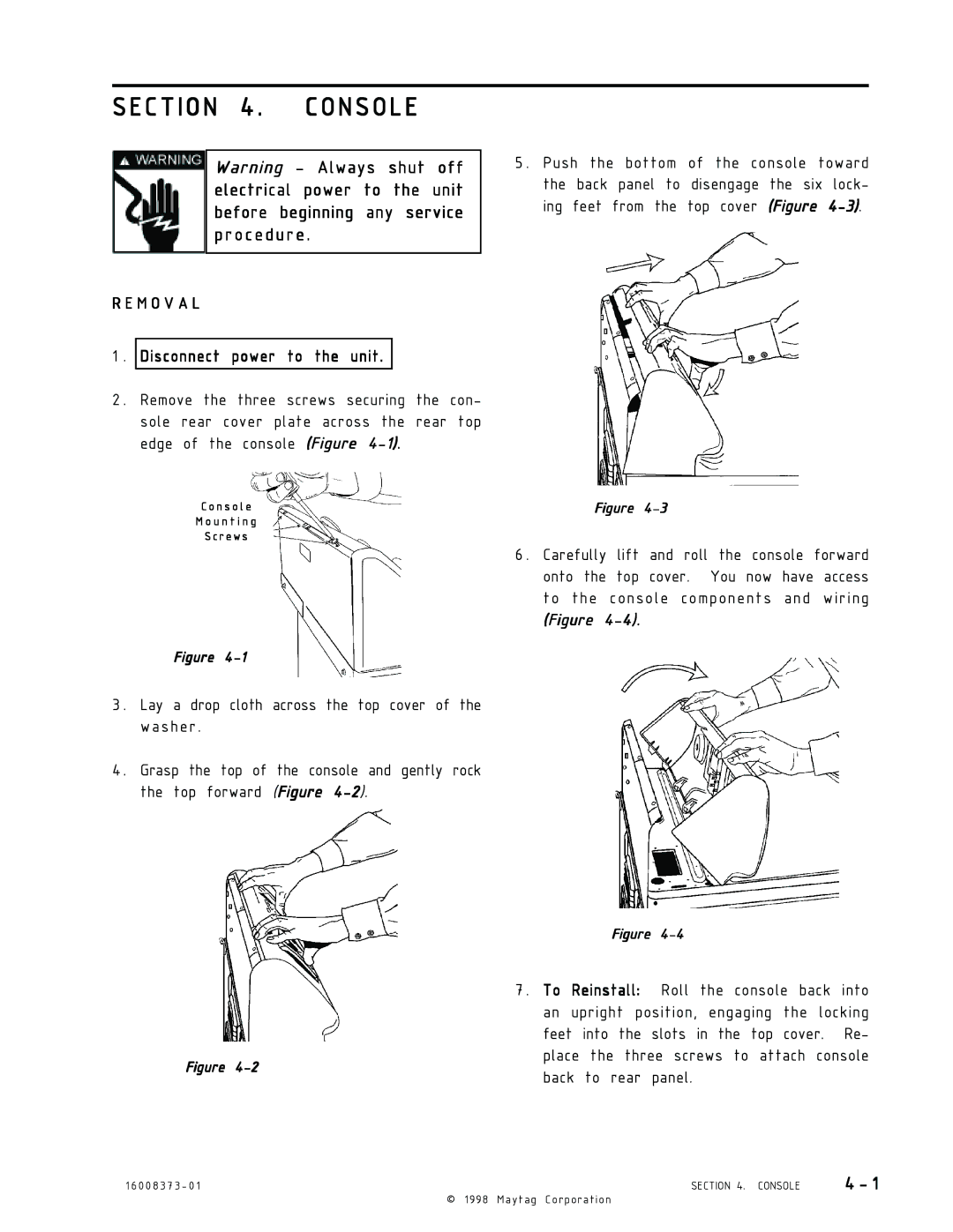
5 . Push the bottom of the console toward the back panel to disengage the six lock- ing feet from the top cover (Figure
1.
2.
Disconnect power to the unit.
Remove the three screws securing the con- sole rear cover plate across the rear top edge of the console (Figure
C o n s o l e
M o u n t i n g
S c r e w s
Figure
Figure
6 . Carefully lift and roll the console forward onto the top cover. You now have access to the console components and wiring
(Figure
3 . Lay a drop cloth across the top cover of the washer .
4 . Grasp the top of the console and gently rock the top forward (Figure
Figure
7 . To Reinstall: Roll the console back into an upright position, engaging the locking feet into the slots in the top cover. Re-
Figure
place the three screws to attach console back to rear panel.
1 6 0 0 8 3 7 3 - 0 1 | SECTION 4. CONSOLE | 4 - 1 |
© | 1998 Maytag Corporation |
|
