4.Remove the front panel and top cover (See
Front Panel & Top Cover Removal).
5.Disconnect the hoses attached to the dis- penser assembly.
6.While lifting, rotate the dispenser assem- bly 90 degrees in a counterclockwise direction.
NOTE: The two tabs on the side wall of the
dispenser bottom may break off if the above
procedure is not followed properly.
5.Remove the hose clamp and injector hose from the spout on the front upper area of the outer tub.
6.In order to provide sufficient space to re- move the injector, place a 5/8" - 3/4" wedge between the spinner and the outer tub.
7.Pinch the two tabs exposed on the outer edge of the outer tub spout and press the injector into the tub. Reverse the previ- ous steps to replace the injector.
FRONT WATER FLUME INJECTOR
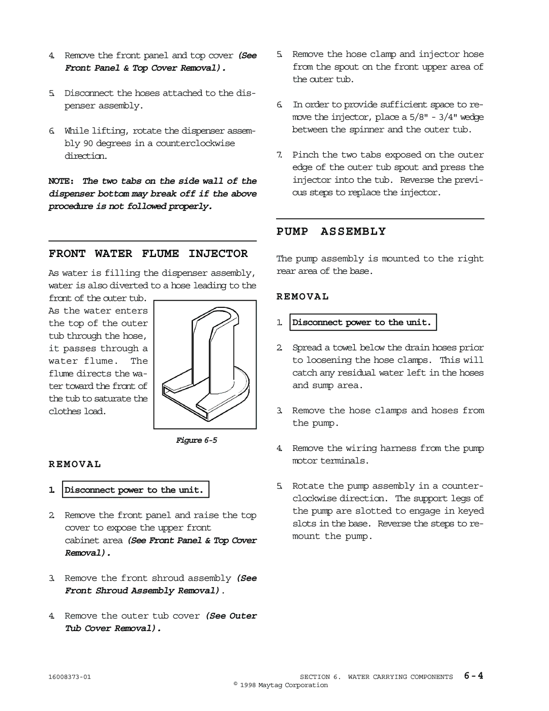
As water is filling the dispenser assembly, water is also diverted to a hose leading to the front of the outer tub.
As the water enters the top of the outer tub through the hose, it passes through a water flume. The flume directs the wa- ter toward the front of the tub to saturate the clothes load.
Figure
REMOVAL
1.Disconnect power to the unit.
2.Remove the front panel and raise the top cover to expose the upper front cabinet area (See Front Panel & Top Cover
Removal).
3.Remove the front shroud assembly (See Front Shroud Assembly Removal).
4.Remove the outer tub cover (See Outer
Tub Cover Removal).
PUMP ASSEMBLY
The pump assembly is mounted to the right rear area of the base.
REMOVAL
1.Disconnect power to the unit.
2.Spread a towel below the drain hoses prior to loosening the hose clamps. This will catch any residual water left in the hoses and sump area.
3.Remove the hose clamps and hoses from the pump.
4.Remove the wiring harness from the pump motor terminals.
5.Rotate the pump assembly in a counter- clockwise direction. The support legs of the pump are slotted to engage in keyed slots in the base. Reverse the steps to re- mount the pump.
SECTION 6. WATER CARRYING COMPONENTS | |
| © 1998 Maytag Corporation |