SECTION 5. CABINET ASSEMBLY
Warning - Always shut off electrical power to the unit before beginning any ser- vice repair procedures.
DOOR ASSEMBLY & HINGES
The door assembly is reversible. It contains an inertial vibration damper comprised of a steel plate suspended with springs. The damper is designed to tune out excessive vi- brations generated by the machine during the spin cycle. Replacement inner door liners are shipped with the vibration damper in place.
R E M O V A L
1.Open the door and remove the center screw of each hinge secured to the inner flange of the front panel in the door opening.
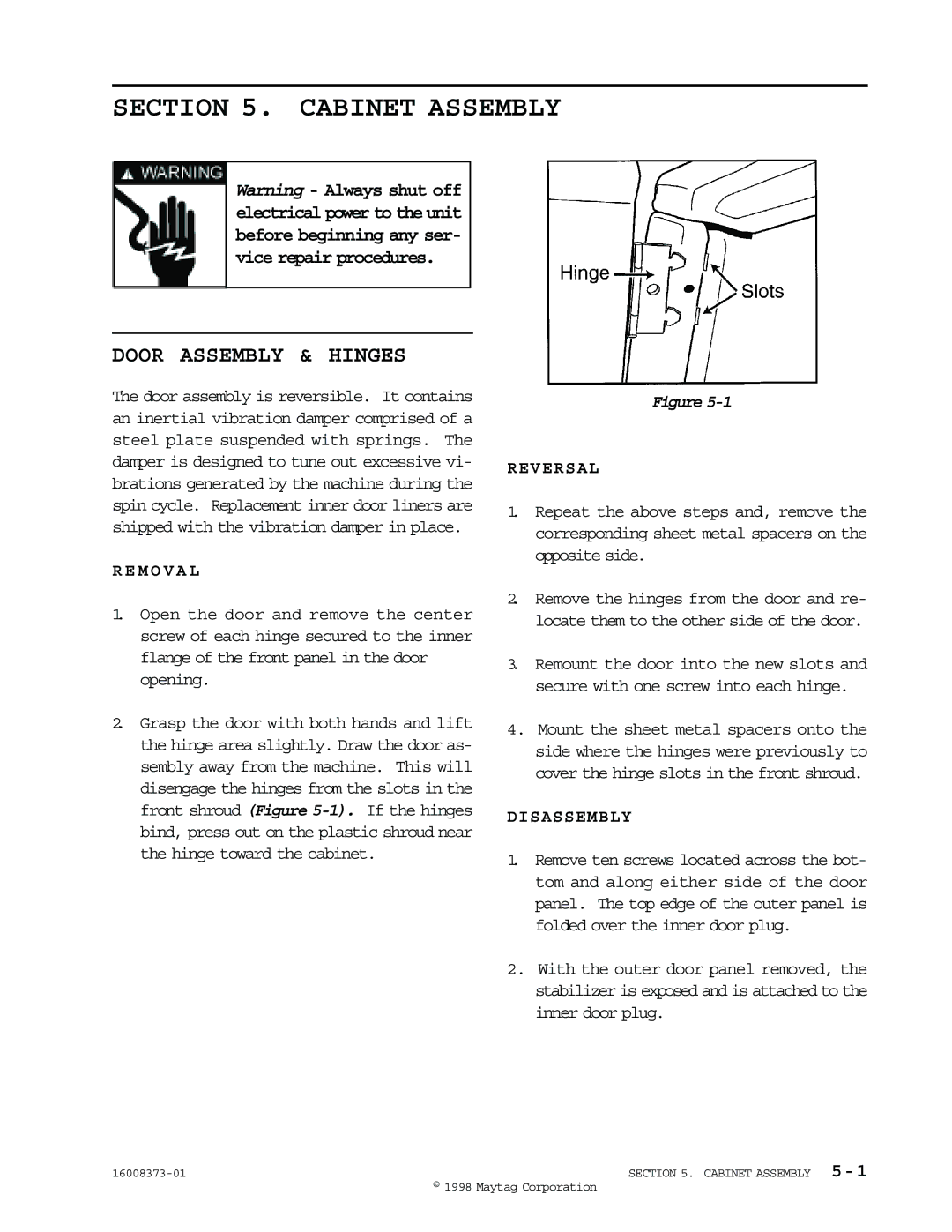
2.Grasp the door with both hands and lift the hinge area slightly. Draw the door as- sembly away from the machine. This will disengage the hinges from the slots in the front shroud (Figure
Figure
REVERSAL
1.Repeat the above steps and, remove the corresponding sheet metal spacers on the opposite side.
2.Remove the hinges from the door and re- locate them to the other side of the door.
3.Remount the door into the new slots and secure with one screw into each hinge.
4.Mount the sheet metal spacers onto the side where the hinges were previously to cover the hinge slots in the front shroud.
DISASSEMBLY
1.Remove ten screws located across the bot- tom and along either side of the door panel. The top edge of the outer panel is folded over the inner door plug.
2.With the outer door panel removed, the stabilizer is exposed and is attached to the inner door plug.
SECTION 5. CABINET ASSEMBLY | |
| © 1998 Maytag Corporation |