Series 15H
Table of Contents
Speed Adjustment using Local Speed Reference
Section
Iv Table of Contents MN715
Overview
Quick Start Checklist
Initial Conditions
CE Compliance
Section General Information
Limited Warranty
Precautions
General Information MN715
Enclosure Size 230VAC 460VAC 575VAC 5kHz PWM 0kHz PWM
Physical Installation
Receiving & Inspection
Series 15H Watts Loss Ratings
Through the Wall Mounting
Control Installation
Keypad Installation Procedure
Shock Mounting
Tools Required
Mounting Instruction For tapped mounting holes
Mounting Instructions For clearance mounting holes
System Grounding
Electrical Installation
Line Reactors
Input Power Conditioning
System Grounding Ungrounded Distribution System
Line Impedance
AWG
AC Main Circuit
460VAC Controls 3 Phase Wire Size and Protection Devices
4575VAC Controls 3 Phase Wire Size and Protection Devices
Control Board Jumpers
Series 15H Control
Tap change procedure size C, D, E and F controls
AC Line Connections
Examples
Phase Installation
Control Transformer Tap Change Procedure size G controls
Baldor Series 15H Control
17.5
Jumper Configuration
Size A, B and B2 Single Phase Power Installation See Figure
Size C2 Single Phase Power Installation
Single phase 3 wire Connections
Single phase 2 wire Connections
9Jumper Configuration
Size C and D Single Phase Power Installation
J100
Size D2 Single Phase Power Installation
Baldor Series 15H Control Single phase 2 wire Connections
Size E Single Phase Power Installation
Baldor
Size F Single Phase Power Installation
Contactor
Motor Connections
19 DB Terminal Identification
Optional Dynamic Brake Hardware
Mm2 Volt
Dynamic Brake Wire Size for RGA, RBA and RTA Assemblies
Voltage Rating Watts Rating Wire Size
Control + / B- and R1 / R2 D1 / D2 Braking Option Terminals
23 Control Signal Connections
Selection of Operating Mode and Connection Diagram
Analog Input #1
Analog Input #2
Analog Input
Analog Outputs
25 Keypad Control Connection Diagram
Keypad Operating Mode see Figure
5KW
Standard Run 3 Wire Operating Mode
Speed 2-Wire Operating Mode
Switch Truth Table for 15 Speed, 2 Wire Control Mode
Function J4-11 J4-12 J4-13 J4-14
Fan Pump 2 Wire Operating Mode
10 Speed Select Table Fan Pump, 2 Wire
J4-11 J4-13 J4-14 J4-15 Command
Fan Pump 3 Wire Operating Mode
11 Speed Select Table Fan Pump, 3 Wire
J4-13 J4-14 J4-15 Command
J4-14 J4-15 Command
Speed Analog 2 Wire Operating Mode
31 3 Speed Analog, 3 Wire Control Connection Diagram
Speed Analog 3 Wire Operating Mode
J4-11 J4-12 Command
Electronic Pot 2 Wire Operating Mode
33 EPOT, 3 Wire Control Connection Diagram
Electronic Pot 3 Wire Operating Mode
15 Process Mode Input Signal Compatibility
Opto-Isolated Inputs
External Trip Input
User VCC = 10 30VDC External Power Source
Digital Outputs
Opto Inputs Closing to Ground Opto Inputs Closing to +VCC
Relay Outputs
39 Opto-Output Equivalent Circuit
Pre-Operation Checklist
Check of Electrical Items
Check of Motor and Couplings
Down Arrow
UP Arrow
Action Description Display Comments
Display Mode
Adjusting Display Contrast
Display Screens
Program Mode
Parameter Blocks Access for Programming
Parameter Status
Changing Parameter Values when Security Code Not Used
Reset Parameters to Factory Settings
Initialize New Software Eeprom
Operation Examples Operating the Control from the Keypad
Speed Adjustment Using Arrow Keys
Speed Adjustment using Local Speed Reference
Security System Changes
Changing Parameter Values with a Security Code in Use
Security System Access Timeout Parameter Change
Parameter Definitions Version S15H-5.06
Parameter Block Definitions Level
Block Title Parameter Description
Decel Time #1,2
Keypad Setup
On makes the keypad REV key active in Local
Input
Condition Description
Output
100% rated power
Level 2 Block Enters Level 2 Menu
Block Title Parameters Description
Block Title
Output Limits
Custom Units
Automatic
Protection
Miscellaneous
Manual
Motor Data
Brake Adjust
Security
Control
Process
Starts
Skip
Frequency
Synchro
No Keypad Display Display Contrast Adjustment
Section Troubleshooting
How to Access Diagnostic Information
Action Description Display Comments
Fault Message Description
Fault Messages
Power Base ID Series 15H
Power Base ID
Indication Possible Cause Corrective Action
Troubleshooting
Control does not recognize hp
Sens
FLT
AC Coil RC snubber
Wires between Controls and Motors
Electrical Noise Considerations
Relay and Contactor Coils
Special Motor Considerations
Special Drive Situations
Section Specifications and Product Data
Control Specifications
Analog Outputs 2 Outputs
Catalog Input Constant Torque Variable Torque Size Volt
Ratings Series 15H Stock Products
Ratings Series 15H Stock Products
Output Input Amp
Ratings Series 15H Custom Control
Ratings Series 15H Custom Control w/Internal DB Transistor
D1/D2 Catalog No Lb-in
Tightening Torque 230 VAC Power TB1 Ground Control J1
Tightening Torque 460 VAC Power TB1 Ground Control J1
Terminal Tightening Torque Specifications
D1/D2 Lb-in
Tightening Torque 575 VAC Power TB1 Ground Control J1
D1/D2
Catalog No Lb-in
Mounting Dimensions Size a Control
Dimensions Size B Control
Dimensions Size B2 Control
Dimensions Size C Control
Dimensions Size C2 Control
Dimensions Size C2 Control Through-Wall Mounting
Customer AIR Inlet Power Connections
Dimensions Size D Control
13.00 24.00 607 23.00 585
Dimensions Size D2 Control
Dimensions Size D2 Control Through-Wall Mounting
Dimensions Size E Control
Dimensions Size F Control
Standard Regen & Non-Regen
Non-Regen with DC Link Inductor
Dimensions Size G Control
Dimensions Size G2 Control
Dimensions Size G+ Control
Dimensions Size H Control
Parameter Description Control Input Voltage
Selection Procedure
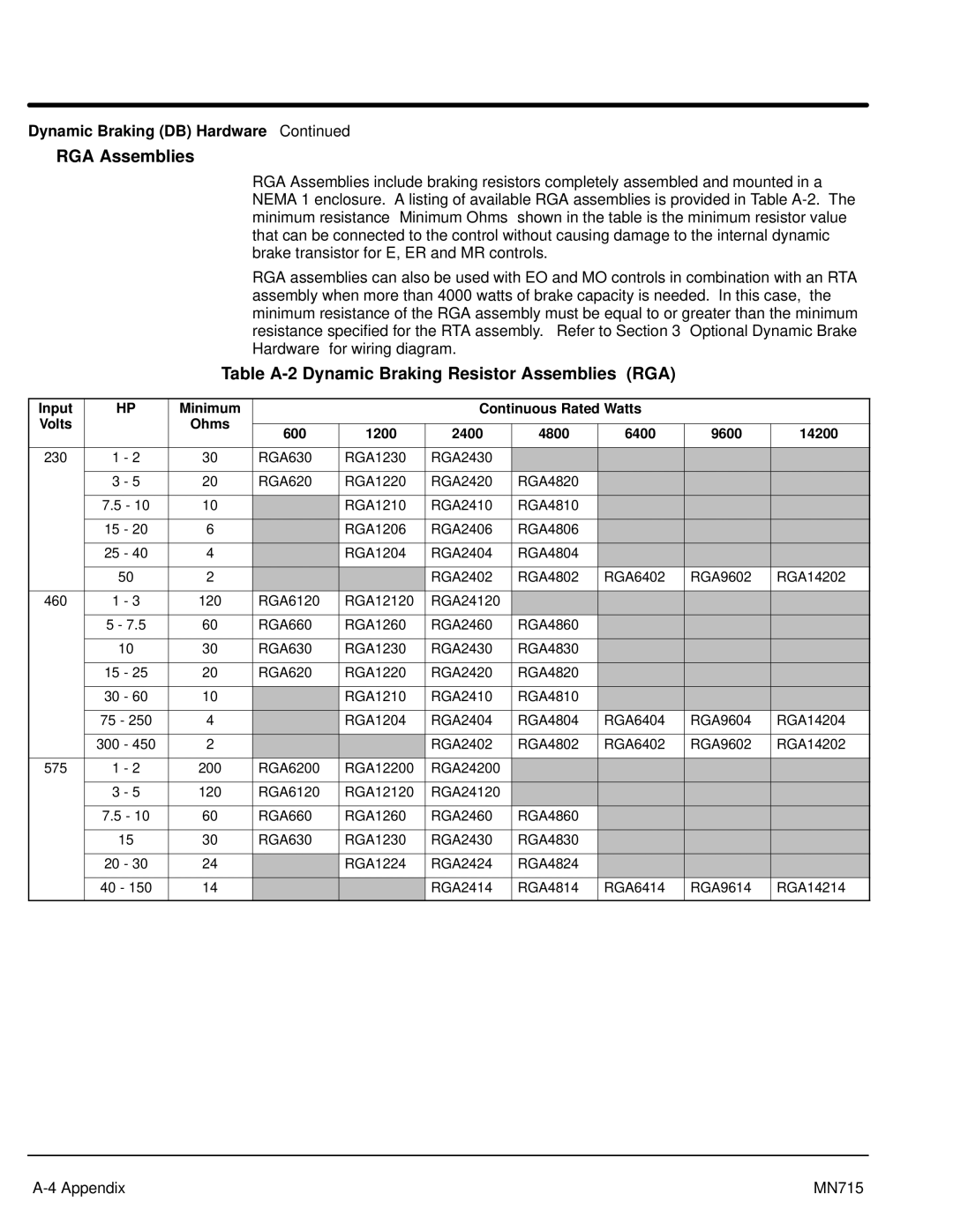
Dynamic Braking DB Hardware
Table A-1
Friction Lb.Ft
Rated HP Watts
15H Catalog Numbers with an ER or MR Suffix
15H Catalog Numbers with an EO or MO Suffix
RGA Assemblies
Table A-2 Dynamic Braking Resistor Assemblies RGA
Dynamic Braking DB Hardware
150 200 250
RBA Assemblies
Table A-3 Dynamic Braking Assemblies RBA
Cont Catalog Watts
Table A-4 Dynamic Braking Transistor Assemblies
RTA Assemblies
Table B-1 Parameter Block Values Level
At Set Speed
Zero Speed
Analog #2 Scale
Output Analog OUT #1
Analog OUT #2
Analog #1 Scale
Table B-2 Parameter Block Values Level
Motor Rated Amps
Adjust Resistor Watts
Setpoint Command
Motor Data Motor Voltage
Skip Band #1
Sync Setup Time
Sync V/F Recover
Skip Frequency Skip Freq #1
Appendix C
Remote Keypad Mounting Template
500
340 810 500 250
Baldor Electric Company MN715 03 C&J10000
Baldor Electric Company
Series 15H Inverter Control MN715