Inverter Control, 15H specifications
The Baldor 15H Inverter Control stands out as a leading solution in the realm of variable frequency drives (VFDs), specifically designed for enhancing motor efficiency and performance in industrial applications. This control unit is engineered to provide robust and reliable performance while ensuring seamless integration with various motor types.One of the main features of the Baldor 15H is its advanced control algorithms, which facilitate precise motor control. This technology allows for smooth acceleration and deceleration, reducing mechanical stress on the system and extending the lifespan of both the motor and connected equipment. The inverter control is adept at handling both synchronous and asynchronous motors, making it highly versatile for different operational needs.
The Baldor 15H incorporates a user-friendly interface that provides operators with real-time data and diagnostics. This feature allows for easy monitoring and troubleshooting, helping to minimize downtime and maintenance costs. The intuitive control panel simplifies parameter adjustments, enabling quick customization for specific application requirements.
Safety is paramount in industrial environments, and the Baldor 15H includes several safety features designed to protect both the equipment and personnel. These features include overload protection, overvoltage protection, and short-circuit protection, ensuring reliable operation even under demanding conditions.
Energy efficiency is another critical aspect of the Baldor 15H. By utilizing pulse-width modulation (PWM) technology, it optimizes power usage, which translates to lower energy costs and reduced environmental impact. This makes it an excellent choice for companies aiming to improve their sustainability practices.
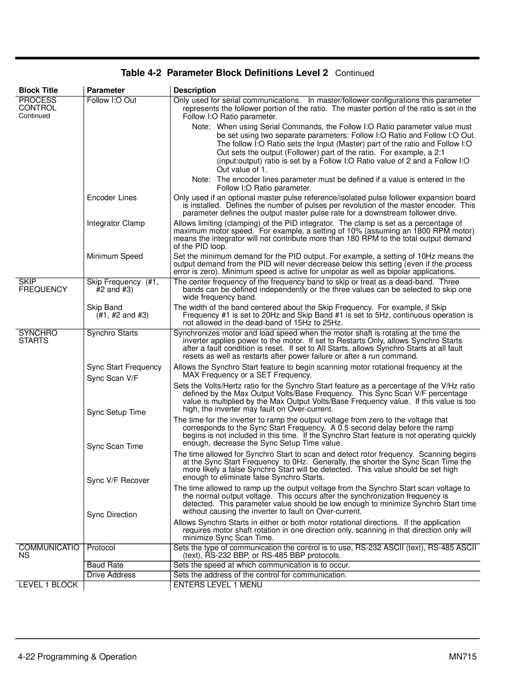
Moreover, the Baldor 15H supports a variety of communication protocols, allowing for easy integration into existing automation systems. This capability ensures that operators can utilize the inverter control within modern industrial networks, enhancing overall system efficiency.
In terms of physical characteristics, the Baldor 15H is designed for durability and reliability. It comes with a robust enclosure that protects against dust, moisture, and other environmental factors commonly found in industrial settings. Its compact design also allows for easy installation in limited spaces.
Overall, the Baldor 15H Inverter Control is a comprehensive solution that combines advanced technology, safety features, and energy efficiency, making it a preferred choice for industries looking to optimize their motor control systems. Its adaptability to different motor types and integration capabilities further solidify its position as a leader in VFD technology.

