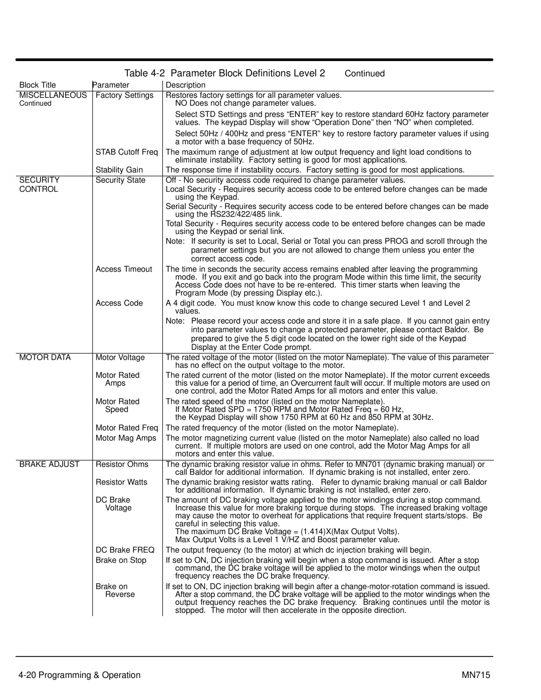
Table 4-2 Parameter Block Definitions Level 2 Continued

Block Title

Parameter

Description

MISCELLANEOUS

Factory Settings

Restores factory settings for all parameter values.

Continued


NO Does not change parameter values.


Select STD Settings and press “ENTER” key to restore standard 60Hz factory parameter


values. The keypad Display will show “Operation Done” then “NO” when completed.


Select 50Hz / 400Hz and press “ENTER” key to restore factory parameter values if using


a motor with a base frequency of 50Hz.


STAB Cutoff Freq

The maximum range of adjustment at low output frequency and light load conditions to


eliminate instability. Factory setting is good for most applications.


Stability Gain

The response time if instability occurs. Factory setting is good for most applications.


SECURITY

Security State

Off - No security access code required to change parameter values.

CONTROL


Local Security - Requires security access code to be entered before changes can be made


using the Keypad.


Serial Security - Requires security access code to be entered before changes can be made


using the RS232/422/485 link.


Total Security - Requires security access code to be entered before changes can be made


using the Keypad or serial link.


Note: If security is set to Local, Serial or Total you can press PROG and scroll through the


parameter settings but you are not allowed to change them unless you enter the


correct access code.


Access Timeout

The time in seconds the security access remains enabled after leaving the programming


mode. If you exit and go back into the program Mode within this time limit, the security


Access Code does not have to be re-entered. This timer starts when leaving the


Program Mode (by pressing Display etc.).


Access Code

A 4 digit code. You must know know this code to change secured Level 1 and Level 2


values.


Note: Please record your access code and store it in a safe place. If you cannot gain entry


into parameter values to change a protected parameter, please contact Baldor. Be


prepared to give the 5 digit code located on the lower right side of the Keypad


Display at the Enter Code prompt.


MOTOR DATA

Motor Voltage

The rated voltage of the motor (listed on the motor Nameplate). The value of this parameter


has no effect on the output voltage to the motor.


Motor Rated

The rated current of the motor (listed on the motor Nameplate). If the motor current exceeds


Amps

this value for a period of time, an Overcurrent fault will occur. If multiple motors are used on


one control, add the Motor Rated Amps for all motors and enter this value.


Motor Rated

The rated speed of the motor (listed on the motor Nameplate).


Speed

If Motor Rated SPD = 1750 RPM and Motor Rated Freq = 60 Hz,


the Keypad Display will show 1750 RPM at 60 Hz and 850 RPM at 30Hz.


Motor Rated Freq

The rated frequency of the motor (listed on the motor Nameplate).


Motor Mag Amps

The motor magnetizing current value (listed on the motor Nameplate) also called no load


current. If multiple motors are used on one control, add the Motor Mag Amps for all


motors and enter this value.


BRAKE ADJUST

Resistor Ohms

The dynamic braking resistor value in ohms. Refer to MN701 (dynamic braking manual) or


call Baldor for additional information. If dynamic braking is not installed, enter zero.


Resistor Watts

The dynamic braking resistor watts rating. Refer to dynamic braking manual or call Baldor


for additional information. If dynamic braking is not installed, enter zero.


DC Brake

The amount of DC braking voltage applied to the motor windings during a stop command.


Voltage

Increase this value for more braking torque during stops. The increased braking voltage


may cause the motor to overheat for applications that require frequent starts/stops. Be


careful in selecting this value.


The maximum DC Brake Voltage = (1.414)X(Max Output Volts).


Max Output Volts is a Level 1 V/HZ and Boost parameter value.


DC Brake FREQ

The output frequency (to the motor) at which dc injection braking will begin.


Brake on Stop

If set to ON, DC injection braking will begin when a stop command is issued. After a stop


command, the DC brake voltage will be applied to the motor windings when the output


frequency reaches the DC brake frequency.


Brake on

If set to ON, DC injection braking will begin after a change-motor-rotation command is issued.


Reverse

After a stop command, the DC brake voltage will be applied to the motor windings when the


output frequency reaches the DC brake frequency. Braking continues until the motor is


stopped. The motor will then accelerate in the opposite direction.

4-20 Programming & Operation

MN715

Page 69
Image 69
Baldor Inverter Control, 15H manual Security, Motor Data, Brake Adjust

Inverter Control, 15H specifications

The Baldor 15H Inverter Control stands out as a leading solution in the realm of variable frequency drives (VFDs), specifically designed for enhancing motor efficiency and performance in industrial applications. This control unit is engineered to provide robust and reliable performance while ensuring seamless integration with various motor types.

One of the main features of the Baldor 15H is its advanced control algorithms, which facilitate precise motor control. This technology allows for smooth acceleration and deceleration, reducing mechanical stress on the system and extending the lifespan of both the motor and connected equipment. The inverter control is adept at handling both synchronous and asynchronous motors, making it highly versatile for different operational needs.

The Baldor 15H incorporates a user-friendly interface that provides operators with real-time data and diagnostics. This feature allows for easy monitoring and troubleshooting, helping to minimize downtime and maintenance costs. The intuitive control panel simplifies parameter adjustments, enabling quick customization for specific application requirements.

Safety is paramount in industrial environments, and the Baldor 15H includes several safety features designed to protect both the equipment and personnel. These features include overload protection, overvoltage protection, and short-circuit protection, ensuring reliable operation even under demanding conditions.

Energy efficiency is another critical aspect of the Baldor 15H. By utilizing pulse-width modulation (PWM) technology, it optimizes power usage, which translates to lower energy costs and reduced environmental impact. This makes it an excellent choice for companies aiming to improve their sustainability practices.

Moreover, the Baldor 15H supports a variety of communication protocols, allowing for easy integration into existing automation systems. This capability ensures that operators can utilize the inverter control within modern industrial networks, enhancing overall system efficiency.

In terms of physical characteristics, the Baldor 15H is designed for durability and reliability. It comes with a robust enclosure that protects against dust, moisture, and other environmental factors commonly found in industrial settings. Its compact design also allows for easy installation in limited spaces.

Overall, the Baldor 15H Inverter Control is a comprehensive solution that combines advanced technology, safety features, and energy efficiency, making it a preferred choice for industries looking to optimize their motor control systems. Its adaptability to different motor types and integration capabilities further solidify its position as a leader in VFD technology.