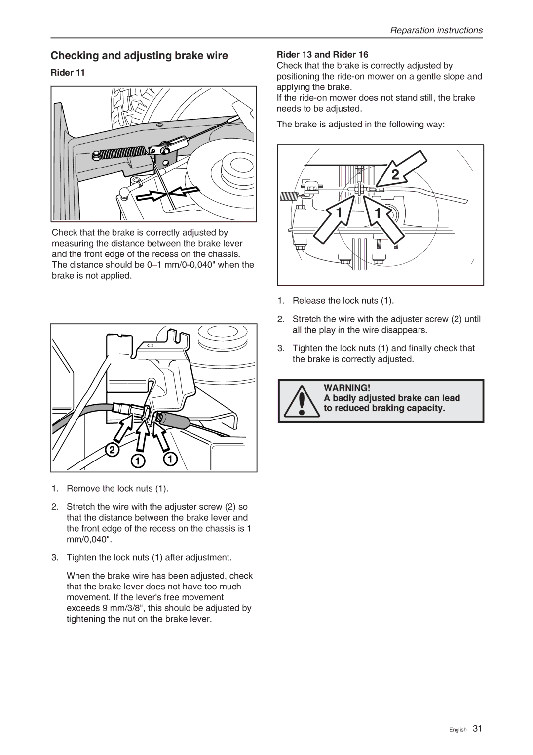
RIDER 13, RIDER 13 BIO, RIDER 16, RIDER 11 BIO, RIDER 11 specifications
Briggs & Stratton is a well-known name in the world of outdoor power equipment, and their RIDER series models, including RIDER 11, RIDER 16, RIDER 13, RIDER 11 BIO, and RIDER 13 BIO, exemplify innovation and efficiency in lawn care. Each model has distinct features tailored to meet diverse gardening needs and preferences.The RIDER 11 is designed for those seeking a compact yet powerful riding mower. With a robust 11 HP engine and a cutting width of 28 inches, it maneuvers easily in tight spaces while still delivering efficient grass cutting. Its ergonomic design ensures comfort during extended use, and the mulching capability allows for clean lawn maintenance.
Next up, the RIDER 16 offers a higher power output with a 16 HP engine, making it ideal for larger lawns. The 33-inch cutting deck increases productivity, allowing users to cover more ground in less time. This model features a hydrostatic transmission, providing smooth and effortless speed control, enhancing the overall mowing experience.
The RIDER 13 stands as a versatile option, featuring a 13 HP engine and a 30-inch cutting deck. This model excels in ease of operation with its user-friendly controls, enabling even novice users to achieve professional results. The adjustable cutting height offers additional customization, allowing for precision mowing depending on the season and grass type.
For environmentally conscious users, the RIDER 11 BIO and RIDER 13 BIO models provide eco-friendliness without compromising performance. Equipped with bio-based components and a reduced carbon footprint, these models ensure a greener approach to lawn care. They retain the essential features of their counterparts, including efficient mowing performance and comfort while emphasizing reduced environmental impact.
Overall, the RIDER series by Briggs & Stratton embodies quality, versatility, and innovation. With robust engines, various cutting widths, and eco-friendly options, these riding mowers are tailored to meet the needs of every lawn care enthusiast. Whether you prioritize power, maneuverability, or sustainability, there’s a RIDER model that can help you maintain a beautifully manicured lawn with ease.

