Table 3—Maximum Capacity of Pipe*

NOMINAL


LENGTH OF PIPE (FT)


IRON

INTERNAL


PIPE

DIAMETER


SIZE

(IN.)

10

20


30


40

50

(IN.)


1/2

0.622

175

120


97


82

73

3/4

0.824

360

250


200


170

151

1

1.049

680

465


375


320

285

1-1/4

1.380

1400

950


770


660

580

1-1/2

1.610

2100

1460


1180


990

900


*Cubic ft of gas per hr. for gas pressures of 0.5 psig (14–in. wc) or less and a pressure drop of 0.5–in wc (based on a 0.60 specific gravity gas). Ref: NFGC.

Risers must be used to connect to furnace and to meter. Support all gas piping with appropriate straps, hangers, etc. Use a minimum of 1 hanger every 6 ft. Joint compound (pipe dope) should be applied sparingly and only to male threads of joints. Pipe dope must be resistant to propane gas.

CAUTION: Connect gas pipe to furnace using a backup wrench to avoid damaging gas controls.

WARNING: Gas valve shutoff switch MUST be facing forward or tilted upward. Failure to follow this warning could result in property damage or death.

WARNING: Never purge a gas line into a combustion chamber. Never use matches, candles, flame, or other sources of ignition for purpose of checking leakage. Use a soap-and-water solution to check for leakage. Failure to follow this warning could result in fire, explosion, personal injury, or death.

WARNING: Use proper length of pipe to avoid stress on gas control manifold. Failure to follow this warning could result in a gas leak resulting in fire, explosion, personal injury, or death.

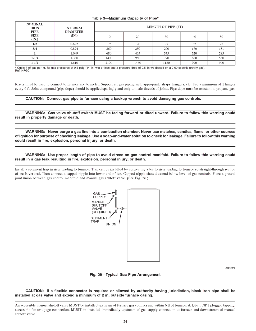
Install a sediment trap in riser leading to furnace. Trap can be installed by connecting a tee to riser leading to furnace so straight-through section of tee is vertical. Then connect a capped nipple into lower end of tee. Capped nipple should extend below level of gas controls. Place a ground joint union between gas control manifold and manual gas shutoff valve. (See Fig. 26.)

GAS

SUPPLY

MANUAL

SHUTOFF VALVE (REQUIRED)

SEDIMENT

TRAP

UNION

A93324

Fig. 26—Typical Gas Pipe Arrangement

CAUTION: If a flexible connector is required or allowed by authority having jurisdiction, black iron pipe shall be installed at gas valve and extend a minimum of 2 in. outside furnace casing.

An accessible manual shutoff valve MUST be installed upstream of furnace gas controls and within 6 ft of furnace. A 1/8-in. NPT plugged tapping, accessible for test gage connection, MUST be installed immediately upstream of gas supply connection to furnace and downstream of manual shutoff valve.

—24—

Page 24
Image 24
Bryant 355MAV instruction manual Maximum Capacity of Pipe, Nominal Length of Pipe FT, Internal Pipe Diameter Size

355MAV specifications

The Bryant 355MAV is a remarkable model that stands out in the HVAC (heating, ventilation, and air conditioning) industry for its efficiency, reliability, and advanced technology. This unit is specifically designed to provide homeowners with excellent comfort while maintaining energy efficiency, making it an ideal choice for residential applications.

One of the standout features of the Bryant 355MAV is its variable speed compressor. This technology allows the system to adjust its cooling output based on the current temperature needs of the home. By operating at multiple speed levels, the compressor can maintain a more consistent indoor climate while using significantly less energy than traditional single-speed systems. This capability translates to lower energy bills and enhanced comfort.

Additionally, the Bryant 355MAV integrates an advanced control system that offers precise temperature regulation. Homeowners can easily set their desired indoor conditions, and the thermostat will communicate with the system to ensure optimal performance. This smart technology not only enhances comfort but also extends the lifespan of the unit by preventing unnecessary strain during operation.

The 355MAV also features significant advancements in sound reduction technology. Designed with noise-absorbing materials and a quiet operation mode, this unit ensures that indoor comfort is maintained without the disruption of loud operational sounds. This makes it a perfect choice for residential settings, particularly in areas where noise sensitivity is a concern.

Energy efficiency is another key characteristic of the Bryant 355MAV. The unit is certified with a high Seasonal Energy Efficiency Ratio (SEER) rating, which means it meets strict energy consumption standards. This not only reflects its eco-friendliness but also contributes to significant savings on utility bills over time.

Moreover, the Bryant 355MAV uses environmentally friendly refrigerants that comply with EPA regulations, further solidifying its commitment to sustainability. This, combined with durable construction and a reliable warranty, ensures that homeowners can expect lasting performance from the system.

In conclusion, the Bryant 355MAV offers an impressive array of features, including a variable speed compressor, advanced control systems, sound reduction technology, and high energy efficiency. These characteristics make it an exceptional option for those seeking a reliable and efficient HVAC solution in their homes. With its commitment to comfort, savings, and sustainability, the Bryant 355MAV continues to be a popular choice among homeowners looking to enhance their indoor environments.