VARIABLE-SPEED


THERMIDISTAT™


CONDENSING


CONTROL


FURNACE


RVS COOLING


O/W2


W2


HEAT/COOL


STAGE 1


Y1/W2


(COMPRESSOR LO)


HEAT STAGE 3


W/W1


W/W1


(FURNACE)


HEAT/COOL


STAGE 2


Y/Y2


Y/Y2


(COMPRESSOR HI)


FAN


G


G


24 VAC HOT


R


R


DEHUM


DEHUMIDIFY

DHUM


DE


24 VAC COMM


C


COM


HUM


HUMIDIFY


HUM


HUMIDIFIER


SOLENOIDVALVE


(24VAC)


N/A


B


S1


OUTDOOR


OUTDOOR


SENSOR


SENSOR


CONNECTION


S2


2-SPEED

HEAT PUMP

O

Y1

W2

Y2

W3

R

C

A01474

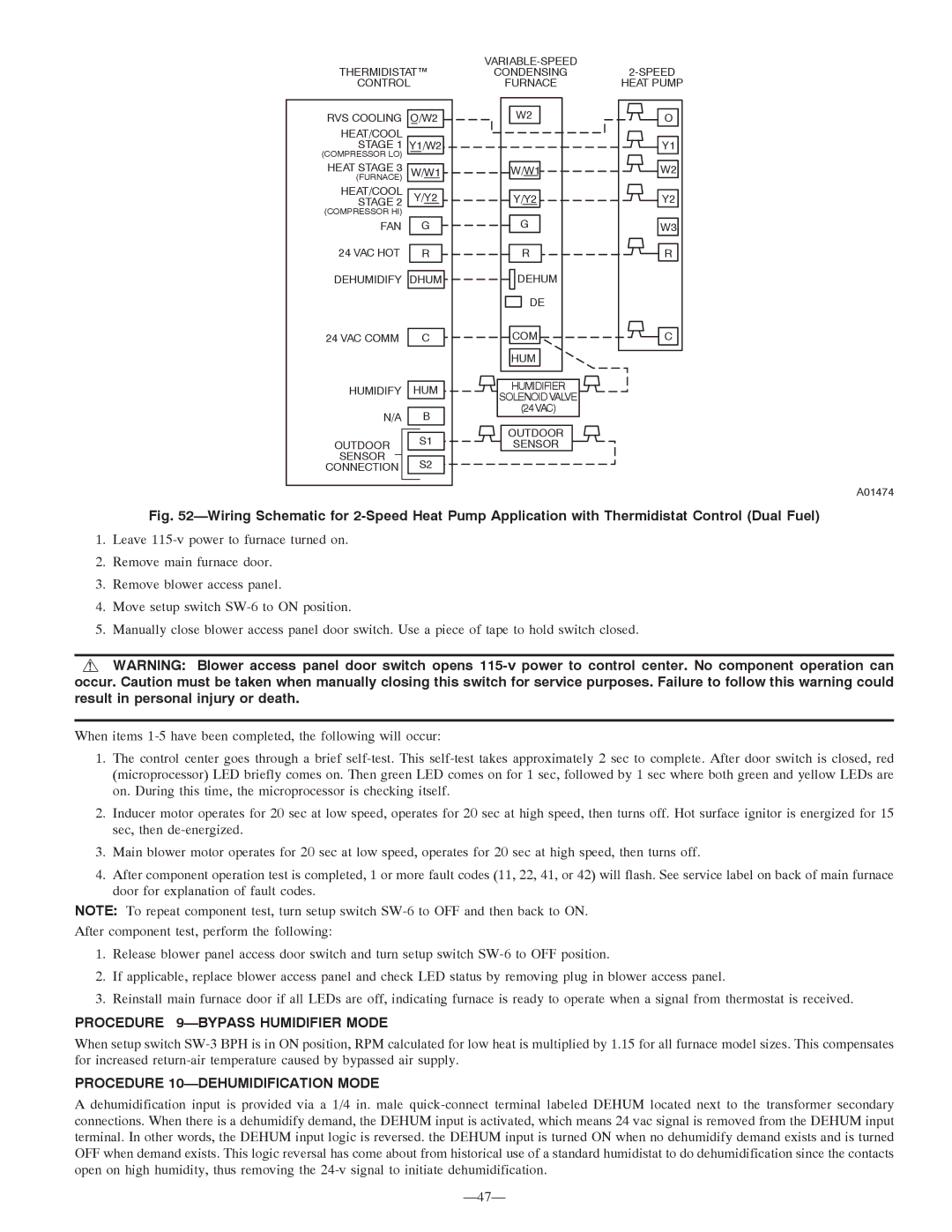
Fig. 52—Wiring Schematic for 2-Speed Heat Pump Application with Thermidistat Control (Dual Fuel)

1.Leave 115-v power to furnace turned on.

2.Remove main furnace door.

3.Remove blower access panel.

4.Move setup switch SW-6 to ON position.

5.Manually close blower access panel door switch. Use a piece of tape to hold switch closed.

WARNING: Blower access panel door switch opens 115-v power to control center. No component operation can occur. Caution must be taken when manually closing this switch for service purposes. Failure to follow this warning could result in personal injury or death.

When items 1-5 have been completed, the following will occur:

1.The control center goes through a brief self-test. This self-test takes approximately 2 sec to complete. After door switch is closed, red (microprocessor) LED briefly comes on. Then green LED comes on for 1 sec, followed by 1 sec where both green and yellow LEDs are on. During this time, the microprocessor is checking itself.

2.Inducer motor operates for 20 sec at low speed, operates for 20 sec at high speed, then turns off. Hot surface ignitor is energized for 15 sec, then de-energized.

3.Main blower motor operates for 20 sec at low speed, operates for 20 sec at high speed, then turns off.

4.After component operation test is completed, 1 or more fault codes (11, 22, 41, or 42) will flash. See service label on back of main furnace door for explanation of fault codes.

NOTE: To repeat component test, turn setup switch SW-6 to OFF and then back to ON.

After component test, perform the following:

1.Release blower panel access door switch and turn setup switch SW-6 to OFF position.

2.If applicable, replace blower access panel and check LED status by removing plug in blower access panel.

3.Reinstall main furnace door if all LEDs are off, indicating furnace is ready to operate when a signal from thermostat is received.

PROCEDURE 9—BYPASS HUMIDIFIER MODE

When setup switch SW-3 BPH is in ON position, RPM calculated for low heat is multiplied by 1.15 for all furnace model sizes. This compensates for increased return-air temperature caused by bypassed air supply.

PROCEDURE 10—DEHUMIDIFICATION MODE

A dehumidification input is provided via a 1/4 in. male quick-connect terminal labeled DEHUM located next to the transformer secondary connections. When there is a dehumidify demand, the DEHUM input is activated, which means 24 vac signal is removed from the DEHUM input terminal. In other words, the DEHUM input logic is reversed. the DEHUM input is turned ON when no dehumidify demand exists and is turned OFF when demand exists. This logic reversal has come about from historical use of a standard humidistat to do dehumidification since the contacts open on high humidity, thus removing the 24-v signal to initiate dehumidification.

—47—

Page 47
Image 47
Bryant 355MAV instruction manual Procedure 9-BYPASS Humidifier Mode, Procedure 10-DEHUMIDIFICATION Mode

355MAV specifications

The Bryant 355MAV is a remarkable model that stands out in the HVAC (heating, ventilation, and air conditioning) industry for its efficiency, reliability, and advanced technology. This unit is specifically designed to provide homeowners with excellent comfort while maintaining energy efficiency, making it an ideal choice for residential applications.

One of the standout features of the Bryant 355MAV is its variable speed compressor. This technology allows the system to adjust its cooling output based on the current temperature needs of the home. By operating at multiple speed levels, the compressor can maintain a more consistent indoor climate while using significantly less energy than traditional single-speed systems. This capability translates to lower energy bills and enhanced comfort.

Additionally, the Bryant 355MAV integrates an advanced control system that offers precise temperature regulation. Homeowners can easily set their desired indoor conditions, and the thermostat will communicate with the system to ensure optimal performance. This smart technology not only enhances comfort but also extends the lifespan of the unit by preventing unnecessary strain during operation.

The 355MAV also features significant advancements in sound reduction technology. Designed with noise-absorbing materials and a quiet operation mode, this unit ensures that indoor comfort is maintained without the disruption of loud operational sounds. This makes it a perfect choice for residential settings, particularly in areas where noise sensitivity is a concern.

Energy efficiency is another key characteristic of the Bryant 355MAV. The unit is certified with a high Seasonal Energy Efficiency Ratio (SEER) rating, which means it meets strict energy consumption standards. This not only reflects its eco-friendliness but also contributes to significant savings on utility bills over time.

Moreover, the Bryant 355MAV uses environmentally friendly refrigerants that comply with EPA regulations, further solidifying its commitment to sustainability. This, combined with durable construction and a reliable warranty, ensures that homeowners can expect lasting performance from the system.

In conclusion, the Bryant 355MAV offers an impressive array of features, including a variable speed compressor, advanced control systems, sound reduction technology, and high energy efficiency. These characteristics make it an exceptional option for those seeking a reliable and efficient HVAC solution in their homes. With its commitment to comfort, savings, and sustainability, the Bryant 355MAV continues to be a popular choice among homeowners looking to enhance their indoor environments.