CONNECTING TO THE NETWORK

4.Check that the link LED on the 10BASE-T Ethernet device and the applicable LNK LED on the SEHI are on. If the LEDs are not on, perform each of the following steps until the LEDs are on:

a.Check that the 10BASE-T device and the SEHI have power.

b.Verify the cabling between the SEHI and the 10BASE-T device.

c.Check the cable for continuity.

If a link has not been established, contact Cabletron Systems Technical Support.

4.1.3Connecting a UTP Segment to an EPIM-T

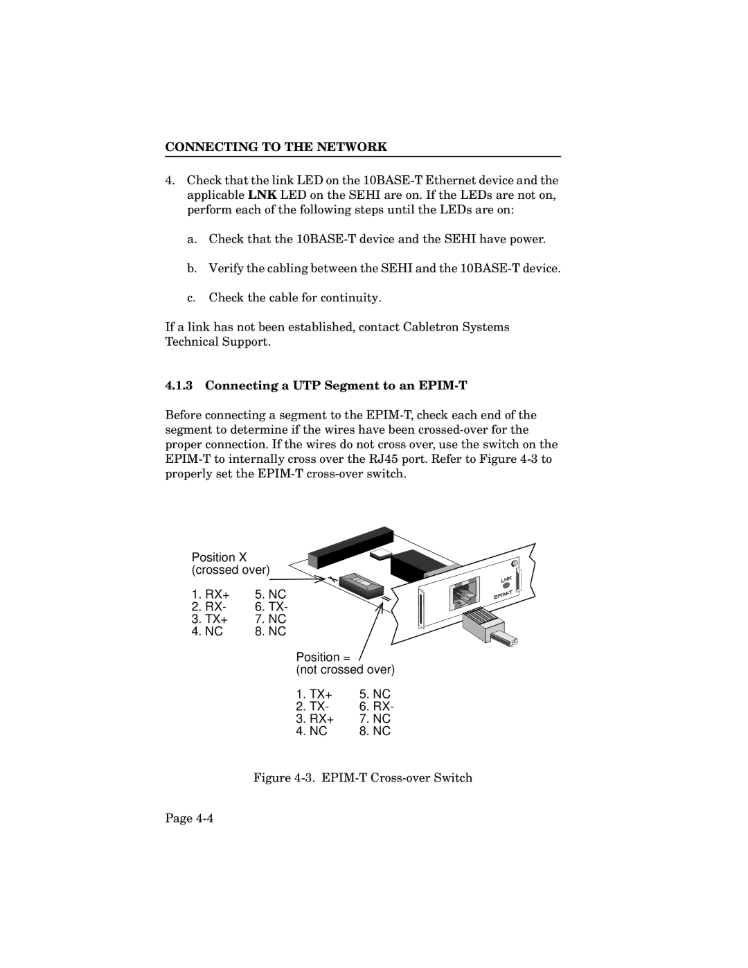
Before connecting a segment to the EPIM-T, check each end of the segment to determine if the wires have been crossed-over for the proper connection. If the wires do not cross over, use the switch on the EPIM-T to internally cross over the RJ45 port. Refer to Figure 4-3 to properly set the EPIM-T cross-over switch.

Position X (crossed over)

1. RX+

5. NC

2. RX-

6. TX-

3. TX+

7. NC

4. NC

8. NC

Position =

(not crossed over)

1. TX+

5.

NC

2. TX-

6.

RX-

3. RX+

7. NC

4. NC

8. NC

Figure 4-3. EPIM-T Cross-over Switch

Page 4-4
Page 45
Image 45
Cabletron Systems SEHI-32, SEHI-22, SEHI-24, SEHI-34 manual Connecting a UTP Segment to an EPIM-T, EPIM-T Cross-over Switch