Chapter 4: Installation
4.Verify that the PWR LED is on, indicating that the SEH is receiving power.
Do NOT connect the interconnect cable between the SEH and
!the SEHI before powering up the SEH. Otherwise damage to
C AUT IO N | the SEH may result. |
|
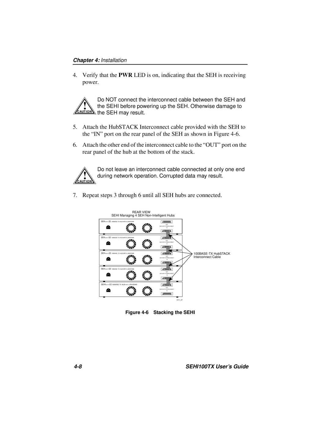
5.Attach the HubSTACK Interconnect cable provided with the SEH to the “IN” port on the rear panel of the SEH as shown in Figure
6.Attach the other end of the interconnect cable to the “OUT” port on the rear panel of the hub at the bottom of the stack.
Do not leave an interconnect cable connected at only one end
!during network operation. Corrupted data may result.
C AUT IO N
7. Repeat steps 3 through 6 until all SEH hubs are connected.
REAR VIEW
SEHI Managing 4 SEH Non-Intelligent Hubs
OUT
SEH100TX INTERCONNECT
IN
OUT
SEH100TX INTERCONNECT
IN
OUT
SEH100TX INTERCONNECT
IN
OUT
SEH100TX INTERCONNECT
IN
OUT
SEHI100TX INTERCONNECT
IN
1511_07
Figure 4-6 Stacking the SEHI
SEHI100TX User’s Guide |