Connecting the SEHI to the Network
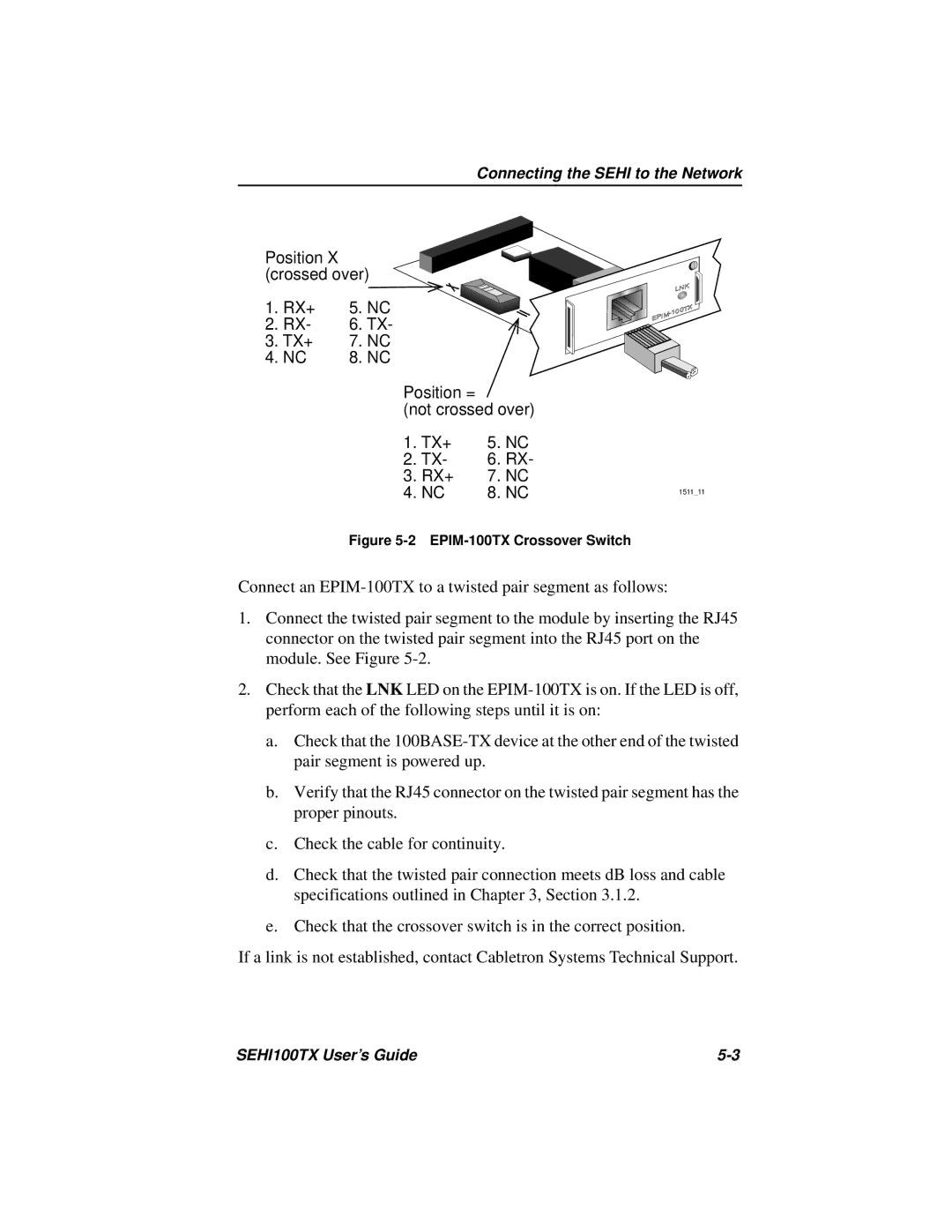
Position X (crossed over)
1. RX+ | 5. NC |
2. RX- | 6. TX- |
3. TX+ | 7. NC |
4. NC | 8. NC |
Position =
(not crossed over)
1. TX+ | 5. | NC |
|
2. TX- | 6. | RX- |
|
3. RX+ | 7. NC |
| |
4. NC | 8. NC | 1511_11 | |
Figure 5-2 EPIM-100TX Crossover Switch
Connect an
1.Connect the twisted pair segment to the module by inserting the RJ45 connector on the twisted pair segment into the RJ45 port on the module. See Figure
2.Check that the LNK LED on the
a.Check that the
b.Verify that the RJ45 connector on the twisted pair segment has the proper pinouts.
c.Check the cable for continuity.
d.Check that the twisted pair connection meets dB loss and cable specifications outlined in Chapter 3, Section 3.1.2.
e.Check that the crossover switch is in the correct position.
If a link is not established, contact Cabletron Systems Technical Support.
SEHI100TX User’s Guide |